Jump-starting a car with a worn out battery in the winter requires a lot of time. The density of the electrolyte after a long storage period significantly decreases, the occurrence of coarse-grained sulfation increases internal the resistance of the battery, reducing the starting current. In addition, winter increases the viscosity of engine oil that requires source of inrush current greater starting power.
Outputs from this position a few:
- heat the oil in the crankcase;
- a jump start from another car with a good battery;
- to have a "pusher";
- wait warming.
- use a launcher charger (ROM).
The last option is the most preferred when storing the car on a paid the Parking lot or in the garage, where there is a connect to the network in addition. The ROM will not only start the car, but also to rapidly recover and not one charge the battery pack.
In most industrial ROM starting battery is recharged from the block power small power (rated current - 3...5 A), which is not sufficient for direct selection of current to the starter of the car Although the capacity of the internal starter batteries ROM is very high (up to 240 Ah), after a couple of starts they all equal to "sit" and to rapidly recover their charge is impossible. The mass of such block exceeds 200 kg, so bring him to the car hard and together.
Starting charging and recovery device (PSWU) proposed by the laboratory "Automatics and telemechanics" Irkutsk center of technical creativity of youth, different from the factory prototype low weight and automatically maintains the operating status of the battery, regardless of storage time and time use. Even if there is no internal battery, able PSVU short to give inrush current up to 100 A. regeneration Mode is a sequence of equal time of current pulses and pauses, which accelerates the recovery of the plates and reduces the temperature electrolyte to the reduction of emission of hydrogen sulfide and oxygen in the atmosphere.
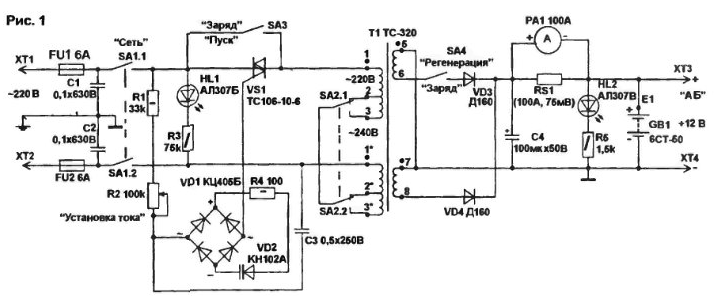
Scheme starting the charger (Fig.1) consists of a triac controller voltage (VS1), power transformer (T1), the rectifier powerful diodes (VD3, VD4) and starter battery (GB1). The current buffer recharging knob to adjust the current to the triac VS1, the current which depends on battery capacity is set by the variable resistor R2 Input and output circuit devices contain capacitors filter that reduces the noise level during work triac controller. Triac VS1 allows you to adjust the charging current when the voltage on the primary winding of the transformer from 180 to 220 V Deeper regulation leads to increased levels of interference.

The enable node of the triac consists of RC-objectives R1-R2-C3. dynistor diode VD2 and bridge VD1 From the time constant of an RC circuit depends on the moment you open the dynistor (relative to the beginning of the half cycle of the mains voltage) included in the diagonal bridge through a current limiting resistor R4 Bridge allows you to synchronize the inclusion of the triac in both half-cycles of the mains voltage. Mode "Regeneration" is used one half cycle of the mains voltage, which allows to clean the plates of the battery from the ensuing crystallization. Capacitors C1. C2 reduce the level of interference from the triac in the network up to allowable limits.
The power transformer T1 is applied from color TV Rubin (with copper windings). Permissible to use a transformer with aluminum windings (type TCA-270). The terminals of the windings to cope in both versions Before rewinding the secondary windings (primary remain unchanged) frames are separated from iron, all the secondary winding (up to foil screens) are removed, and the vacant seat tightly wound copper wire cross section 1.8 . 2.0 mm2 in a single layer (up to fill) of the secondary winding.
The voltage of one winding turns 15... 17 V. Connecting the two windings in Daisy chain, you can get twice the voltage. A common point windings is connected to the bus "-" batteries, conclusions (6. 8) to switch modes SA4 and the diode VD4.
To control the charging and starting current in the circuit "+" tires installed shunt with RS1 device RA1, designed for a maximum current of 100 A. the LEDs HL1 and HL2 indicate the presence of voltage in the primary and secondary circuits. Network the switch SA1 is designed for a current of 10 A. the Switch mains voltage SA2 (type TK or PT) allows you to set the maximum voltage at the transformer in according to the mains voltage. The internal battery unit connected GB1 to "+" bus via removable jumper E1. For 3.. 5 simultaneous launches enough battery ST or ST. The resistors in PSVU - type MLT or JV. the capacitor C1. C2 - KBG-MP (with three pins), C3 - MBGO. C4 - C50-12, K50-6. Diodes D160 (without radiator) can be replaced with any permissible current of not less 50 A, triac - type vehicle.
The connection of the secondary circuit must perform a copper bus bar cross section of at least 16 mm2, primary - stranded wire cross section of 2 mm2. Connections to PSVU the vehicle battery is powerful Crocodile clip (operating current up to 200 A). To connect to your network uses a three-core cable in cold-resistant vinyl insulation for currents up to 10 A. In the device necessarily the presence of ground terminals.
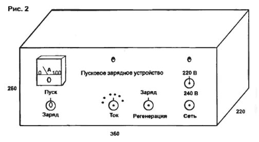
The device is assembled in body size 360x220x260 mm (Fig.2), starting the battery is installed next. All radio components, in addition to installed on a faceplate mounted on the textolite plate thickness of 2 mm.

Adjusting to the assembled device is connected (in the correct polarity!) the internal battery GB1, and checked the adjustment of the charging current resistor R2. Next is controlled by the charging current in the charge mode, start-up and regeneration. If it does not exceed 10 to 12 A. PSVU - normal
When the device is connected to the vehicle battery current should increase first in 2...3 times, and after 10...30 min to decrease to the original value (at the expense pre-charging the batteries) Then the switch SA3 is translated in mode "start" and start the engine of the vehicle. If you have failed, there is an additional charge during the same time, and attempt repeats. After winding of the clamps are removed from the battery and fixed on isolated rack to eliminate random circuit.
Internal battery switch SA4 transferred to regeneration mode with a current in the range of 0.02 ( - the battery capacity GB1).
Literature
Author: V. Konovalov, Irkutsk


