Modern domestic cars equipped with a wiper, providing two speed of its work, as well as both continuous and the pulsed mode. This creates a comfort when driving in bad weather conditions.
Meanwhile, many older vehicles, and some relatively new wiper only works in one - continuous mode. The addition of the unit controls the wipers simple electronic breaker allows you to get adjustable intermittent.
Most previously published electronic control units windscreen wiper [1] inherent drawback. The fact is that when the driver turns the wiper the time of supplying current to the motor is delayed for the time-dependent position of the variable resistor that sets the duration of pauses between cycles of movement of the brushes [2, 3]. This creates certain the complexity in the operation, distracting the driver for additional manipulation controller pause.
Further improvement of these units and their operating experience has shown that one cycle of movement of the brushes when you initially turn on the wiper not always enough to clean the windshield. As a rule, it requires three driving cycles under normal conditions up to five at the most unfavourable.
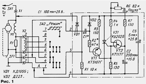
Described below is the circuit breaker (see the scheme in Fig. 1) connected to the wiper provides an adjustable intermittent and simultaneous the motor M1 at the time of four or five continuous driving cycles brushes with each successive switching on, after which the device automatically switches to single cycles with pauses between them. Provided the design of the wiper speed - fast or slow - remain unchanged, it is only possible to define the duration of pauses between cycles in these modes. Pause set a variable resistor whose handle is withdrawn on the dashboard of the car.

The device is designed to work with the existing mode switch wiper, and the connection diagram is shown on the example of M-2140. The numbering of the conductors of the connectors and connect to the switch correspond to the factory wiring diagram of the car.
The conductor And connecting pin 1 of connector x2 with pin 1 of the switch SA2 (see Fig. 1), when connecting the interrupter to remove.
The circuit breaker consists of trinistorny switch (VS1), generator opening pulses on the unijunction transistor (VT2), the node's initial inclusion the SCR (VT1), elements of protection from EMF (VD1, C3). In the original the state of the mode switch SA2 wiper is zero position ("Off"). The contacts of limit switches SF1, mechanical associated with gear motor, open.
When contacts SA1 ignition switch the vehicle voltage is supplied the output 1 of circuit breaker and through the motor windings, pin 4 of connector x2 - on pin 2. Diode VD1 is closed, and capacitor C1 begins to charge through the diode VD2 and the resistor R1. The time constant of charging is small (0,5...1 (C), and the capacitor quickly charges to the Board voltage. The breaker is ready for operation.
If you now move the switch SA2 in position "1" - low speed movement of brushes - closes its contacts 1, 4 and 2, and therefore will be closed and conclusions 2 and 3 of the breaker. Disconnects the charging circuit of the capacitor C1; plus lining the charged capacitor C1 is connected through a resistor R3 with the emitter of the transistor VT1, and the negative through resistor R2 from its base.
Therefore, the capacitor C1 begins to discharge through resistor R2, the emitter the transition of the transistor VT1 and a resistor R3. Another discharge circuit, as the diode VD2 is closed. The transistor opens and opens SCR VS1, which is connected parallel contacts SF1. As a result, the shaft of the motor M1 starts to rotate, closed contacts SF1, closing conclusions 3 and 4 of the breaker. It leads to the closing of SCR VS1, and the engine continues to run until opening contacts SF1.
Simultaneously continues to discharge capacitor C1 according to the above the chains. The time constant of discharge of the selected higher - 7...9 S.
When the wiper finish a full cycle of movement and open contacts SF1, voltage again goes to the anode of SCR. Because discharge of the capacitor C1 is still ongoing, open the transistor VT1 re-open SCR. Not having time to stop, the motor turns back on and the cycle repeats.
This cyclically continuous motor operation will continue until until the capacitor C1 is fully discharged and the transistor VT1 will remain closed at the next appearance of a voltage at pin 3 of the device. With this the moment begins to charge the capacitor C2 of the pulse generator. Upon reaching a threshold voltage on this capacitor will open the transistor VT2 and the resistor R5 is formed impulse, which opens SCR VS1.
The motor is switched on again, and the cycle is repeated, but now with intervals specified charging circuit R6R7 of the capacitor C2. At minimum the resistance of the resistor R6 pause between cycles is virtually absent, when the maximum pause is equal to about 15 C.
If you put the switch SA2 in the "0" position, the unit will go into the source the state of the capacitor C1 is quickly charged to the supply voltage through the remaining circuit current does not leak. The breaker is ready for inclusion wiper.
When installing the switch SA2 to "2" (includes wiper in a quick movement of the brushes and the motor headlight washer) and to position "3" (added the motor windshield wiper) all the processes in the device proceed similarly.
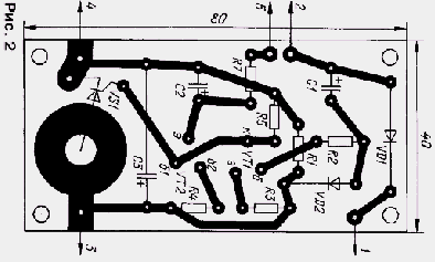
All elements of the breaker, in addition to the variable resistor R6, placed on a printed Board of foiled fiberglass 1.5 mm thick. a Drawing Board is depicted in Fig. 2. In the device, you can use any power resistors 0.125 or 0.25 watts. In the choice of capacitors C1 and C2, which part time-setting circuits, note that when reducing sтемпературы their capacity is reduced, some types significantly. For this reason, from the use of the capacitors C50-6 should obviously be abandoned.

Instead CTG will fit any low-power p-n-p transistor with a pulse current the collector of at least 100 mA and a static current transfer ratio base not less than 100.
When specified on the diagram the values of resistors and capacitors, the number of continuous cycles at the moment of switching of the wiper is equal to 4-5, and the duration of the pause can be adjusted in the range 0...15 S.
The knob of the variable resistor R6 is placed on the instrument panel near the handle mode switch.
Literature
Author: A. Kuzema, Gatchina, Leningrad region.


