To date, the Zhiguli cars remain the most common "foreign car" running for many years on our roads. Especially a lot of "old ladies" models VAZ 2101-2107.
For 30 years, my "deuce" has changed many owners. Were replaced with many nodes and the details. If on the hardware it can be understood, the repeated failure of relay wiper RS, relay control RR was asked to renounce their services.
Analysis of the Amateur radio literature over the last 20 years have shown a tendency to substitute relay RS electronic devices. First it was the transistor multivibrators. As the load in one of his shoulders and stood electromagnetic relay or power transistor. Then as the key began to use the thyristor.
The most simple scheme wiper relay [1] contains the thyristor and one CO low-power transistor. The duration of the pause in the cycle of operation of the wiper depends on the discharge time of the timing capacitor, and it may be adjusted. This is good, as such a need appears when you change the intensity rain or snow. But the fact that this simple scheme is very critical to the parameters thyristor and requires painstaking selection of many elements, of course, bad.
Adding another transistor [2] allows to exclude selection of items.
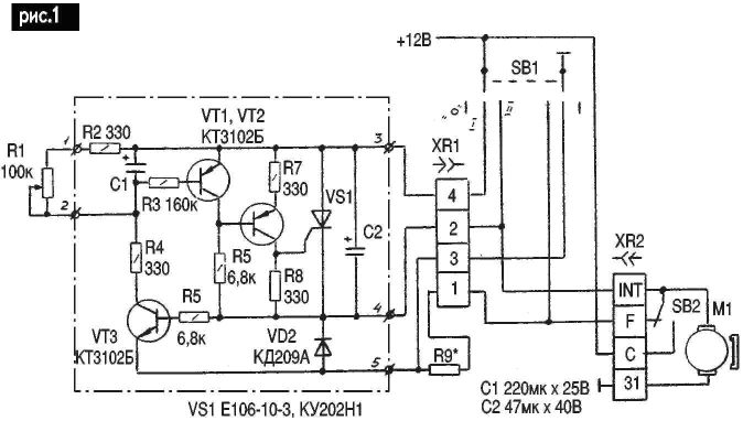
The proposed scheme electronic relay wiper (Fig.1) difficult to several elements, but has a higher reliability, can provide dynamic braking of the motor. Any alterations staffing scheme electric car [3] is required.
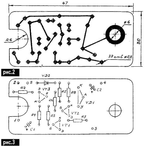
Actually the scheme wiper relay, highlighted in Fig.1 dash-dotted line, mounted on a printed circuit Board (Fig.2 and 3) of foil fiberglass and placed in the housing of the removable relay RS. Plug connector XR1 together with connecting wires from the relay RS.


The device operates as follows. Regular double rocker switch SB1 modes of the wiper has three positions: "0" -wiper off; I - cyclical (pause) mode of operation; II - continuous operation wiper. In position II power supply (+12 V) is applied directly to the the motor M1 through the contact wiper int connector XR2. Thus limit switch SB2 does not affect the operation of the engine. In position I the mode switch SB1 voltage +12 V are fed to the contact 3 schematic electronic relay. This state SB1 shown in the drawing.
As to the original point, the capacitor C1 is discharged, on the basis transistor VT1 there is no voltage on its emitter, and VT1 is locked. In this case, the transistor VT2 is unlocked by the base current through the resistor R5 and the winding the motor M1. Accordingly unlocked the thyristor VS1, receiving positive potential to the control electrode through a resistor R7. The thyristor instantly goes into the conducting state and "remembers" it. Terminal 4 of the scheme electronic voltage relay +12 V is supplied to the motor winding, and the wiper starts to move brushes.
Almost simultaneously switches limit switch SB2. In this case, the thyristor VS1 zamorachivatsja contacts "int C" (connector XR2) and passes in non-conductive condition, but the supply voltage the engine does not stop. Through a resistor R6 is unlocked transistor VT3, providing fast charging up to the voltage of the power supply capacitor C1 through the resistor R4, the unlocking of the transistor VT1 through the resistor R3. This turn leads to the locking of the transistor VT2. After making brushes double stroke and return them to the original position changes the status of the end switch SB2, contacts "int-C" open (a int-F isolates. The motor M1 is stopped, since the thyristor VS1 is non-conductive condition. Locked VT3. Begins the formation of a pause in the cycle of operation wiper.
Capacitor C1 discharges through the resistors R1, R2, R3 and the base junction of transistor VT1. Discharge time (pauses) can be adjusted from 0.5 up to 20 with potentiometer R1. Reduction of a charge of C1 leads to the locking of the transistor VT1. Accordingly driver transistor VT2 and the thyristor VS1. Engine the supply voltage is connected across the thyristor VS1, and through a very small the period of time the power is provided by a limit switch SB2. The process of motion brushes repeats.
The capacitor C2 reduces the arcing contacts limit switch SB2 and interference the operation of the switch wiper in the car. Its value is not critical, it can reduce 10 times.
The protective diode VD2. You can replace CD, CD, CD, CD and similar. As VS1 can be used thyristors CU with any letter. Application KU possible, but reliability will be lower. The printed circuit Board allows to apply the thyristors in a plastic housing type CON-1 or T-10. Thus the circuit Board can be shortened by 15 mm., the Maximum pause duration when the desire can be increased. It is enough to increase proportionally the resistance of the potentiometer R1 or the capacitance of the capacitor C1. Now a few words about dynamic braking of the motor. The fact that the drive mechanism brushes wiper cars "Lada" has a small friction loss. If stop the engine, use only the engine is de-energized at the source the extreme position of the brushes, the inertia of the rotor of the motor some more crank, and the brushes will advance further 3-5 mm. In principle it is not creates much inconvenience to the driver, but this deficiency is easily corrected. In standard design with relay RS was used for this contact "int-F" limit switch, which, when the pause was short circuited winding is de-energized of the motor.
In the proposed scheme, the electronic relay for dynamic braking of the motor simply install the resistor R9. Its value is not critical from 4.7 to 10 Ohms. In fact, the resistor dissipates little power, since the current through him in normal operation, the relay flows only briefly, but not to eliminate the emergency and the condition of the wiper, for example, "sticky" contact int-F" limit switch. It is therefore advisable to use powerful resistor type sew-10.
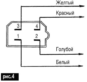
As mentioned earlier, the use of electronic relay wiper not requires changes to the staffing wiring of the car "Lada". Post the failed relay RS be apart from him to unsolder wiring of the four wires with plug connector. The colors of the wires and their connection with the plug shown in Fig.4.

If dynamic braking is not used, and this is justified for simplify the design, the end of the unused wires should be isolated.
The wiring harness was being served to the electronic relay circuit Board, and the Board itself is placed in case RS and closed by an insulating cover-bottom on the size of the Board. Potentiometer R1 is placed in any convenient position for the driver location on the dashboard of your car, for example, near the mode switch wiper.
Were manufactured and installed on vehicles more than five copies of the electronic relay wiper. Selection of items was conducted. All drivers note a wide range of pause intervals. The operation of the wiper motor has become more sustainable.
In conclusion, it should be noted that the proposed electronic relay is the most simple technological solution to the problem, therefore, found in the literature of digital circuits relay was not seen as unnecessarily complicated, moreover, neither the exact value of the pause nor its stability for the driver inconsequential.
Literature
Author: E. L. Yakovlev, Uzhgorod


