Currently, many vehicles are equipped with various systems alarm systems, which are usually triggered reproduce tonal combinations sound signals. Here is described a device that informs the driver in speech form. It can also be used, for example, motion detector car is in reverse, as well as in the flat call, in electronic toys.
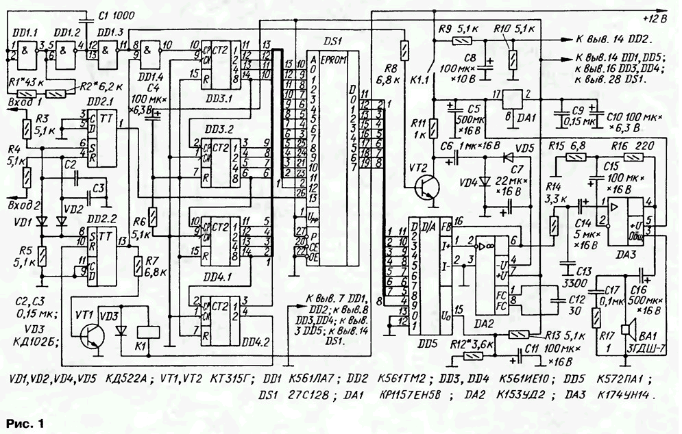
The speech detector is applicable in all cases that require the storage and multiple play a small sound files. The device (see diagram on Fig. 1) contains a node running on the triggers DD2.1, DD2.2, the transistor VT1 and relays K1, a clock generator logic elements DD1.1, DD1.2 with inverter DD1.3, node counting DD3, DD4 that generates sequential addresses for permanent storage device with UV Erasure DS1, digital-to-analog Converter DD5 amplifier at the shelter DA2 and powerful amplifier 3H DA3. The power supply of the detector consists of a voltage regulator DA1 (5 In) and shaper minus pyativolnovye voltage VT2 transistor and diodes VD4, VD5 to power OU DA2.

The signal to start the operation of the device is a pulse with electric lock the driver door lock. The majority of alarm systems that momentum has the amplitude of 12 V and a duration of about 0.5 seconds.
Initially, power is supplied only on RS-triggers DD2.1 and DD2.2. They are not have chains presets, so when the supply voltage trigger DD2.1 can be in any condition. The same trigger DD2.2, once in a zero condition, and will remain, and if single, the device fulfills one cycle and returns the trigger to 0 supply high level input R with output 2 counter DD4.2.
When triggered, Central locking momentum with his blocker arrives at the inputs of alarm: when you open the door - the input 1, and when closing - 2.
When you open the car door, the control pulse switches trigger DD2.2 in one state. With direct output of the trigger signal high level opens the transistor VT1. Relay K1 is actuated and through the contacts K1.1 applies power to the amplifier 3H DA3 and a voltage regulator DA1. Starts work address counter DD3, DD4, ROM DS1 DAC and DD5. The chain forms C4R6 the signal reset DD3 and DD4, delaying the start of their work with 0.5 to setting the operating mode of the node device.
A clock generator begins to produce rectangular pulses with a frequency of 11 kHz. With buffer element DD1.3 they arrive at the base of the transistor VT2, which part of the driver negative supply voltage OU DA2.
The high signal from the direct output of the flip-flop DD2.2, acting on the bottom the schema of the input element DD1.4, permits the passage of clock pulses to the input of line counters DD3.1, DD3.2, DD4.1, DD4.2. The output counters are formed sequential address signals with 1FFF 0000 by that arrives at your address inputs AO-A12 ROM DS1.
Simultaneously with the trigger DD2.2 in state 1 switches and trigger DD2.1 (if it is in the initial state was zero). With its direct output voltage high level is supplied to the address input A13 ROM and sets DS1 senior the discharge start address 2000 recorded audio file.
Thus begins the reading of information from the ROM in the address period from 2000 to 3FFF. The signals from the outputs D0-D7 ROM arrive at the inputs of the DAC DD5. And DAC, and Oh DA2 included under the standard scheme. The analog signal through the filter R14C13 is supplied to the amplifier 3H DA3 and, reinforced, reproduced dynamic head BA1.
After reading information from the ROM output 2 counter DD4.2 appears high level, which translates the trigger DD2.2 to 0. Low level with direct access prohibits the passage of the clock pulse generator to the input counter, closes the transistor VT1, causing relay K1 releases the anchor - the device shuts down and goes into standby mode.
When closing the car doors the control pulse with lock lock to the input 2 of the device and translates the trigger DD2.1 to 0, a DD2.2 in state 1. The process of operation of the device occurs in the same way as when opening door. The only difference lies in the fact that the input A13 ROM DS1 with direct access trigger DD2.1 receives a signal of low level, setting the MSB of the start address 0000. For this reason, when the door is closed, the information from the ROM read in the span of addresses from 0000 through 1FFF.
As a result, the alarm plays two short messages, one when you open the door, the other at closing.
For programming the ROM is formed using any audio file in editor the 8 bit WAV format. The file size depends on the capacity of the ROM and the sampling frequency (clock frequency); at a frequency of 8 kHz 8 kbps (voice information), when the frequency of 11 kHz to 11 kbps (music, speech with high quality). Then the editor files that allows you to work with files in hexadecimal system (such editor complement most programmers), addresses 0000-0039, which store proprietary information of WAV format, write code 7D, which corresponds to the pause. After this editing information transfer in the ROM, addresses 2000-3FFF when you open the door and 0000-1FFF when closing.
With items shown in the diagram, a sampling rate of 11 kHz, and the device generates two audio fragment length 0.7 s In device perhaps the use of ROM circuits with a larger capacity, for example, S, 27S512. For increase address space use the outputs 2, 4, 8 counter DD4.2.
Resistors R3-R5 to the input of the alarm limit pulse to level 6 V. the Capacitors C2 and C3 weaken the effect of interference. Capacitors C5, C7 - C10 - filtering in the power supply.
You can use all of the capacity of the ROM to play one sound the snippet. For this purpose output 2 counter DD4.2 is connected to the input A13 ROM DS1 and output 4 - input R of the flip-flop DD2.2. Elements DD2.1, R3, VD1 and C2 be unnecessary.
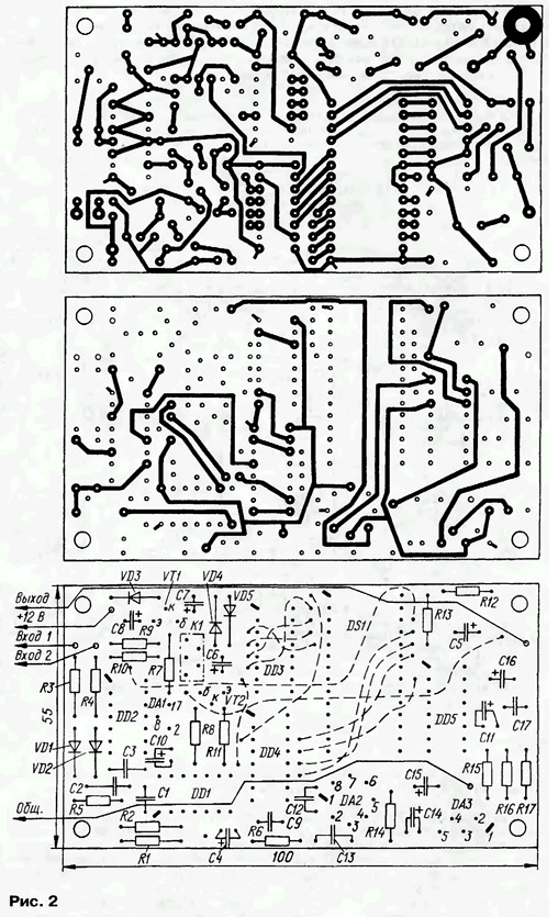
The device is assembled on the PCB of bilateral foil fiberglass thickness of 1.5 mm. Drawing Board shown in Fig. 2. Pay the readers ' attention to the fact that almost all transitions from one side printing another welds made relevant findings of the details from both sides. Only one point - she is close to becoming a profitable output capacitor C4 - requires the introduction of additional wire retainers.

Capacitor C1 should be chosen with low TKE. Oxide capacitors - C50-35, C50-40, rest KM, K10-17. Transistors VT1, VT2 any of the applicable series KT315, KT3102. The ROM chip IS acceptable to use with a small number defective memory cells, while the sound quality significantly deteriorates. It you can replace domestic analogue CHA. To provide a quick change sound fragments, should be provided on the circuit Board panel for the ROM.
Chip DA3 operates in intermittent mode, so the heat sink is not needs. Diodes - any of a series KD521, KD522. Relay K1 - RES, passport RS4.569.501, or to any other voltage 9...12 V
Instead KREW you can use stabilizers CREA, CREB, REG and CREA, CREB, CREA, and CREB foreign 78L05, but given their different Pinout (see "Radio", 1999, No. 2, pp. 69-71). Note, incidentally, that in some reference books of recent years is given Pinout stabilizers series KREN other than that specified in the log "Radio". Thus, the input (pin 17) corresponds to output 1 General output (8) - 2, output (2)-3.
Some alarm systems accompany the opening and closing of locks doors from their own siren. If you cannot disable these the signals must be applied to the alarm relay K1 not with one but with two contact groups (for example, RAS, passport RS4.569.438), and a second group to disable the siren on the alarm.
Dynamic head BA1 any power not less than 2 watts and the resistance not less than 4 Ohms.
The device is mounted in a plastic box and installed behind the instrument flap near the electric drive motor of the wiper.
The establishment of the indicator involves the selection of resistors R1 and R2, which set the frequency of the master oscillator - 11 or 8 kHz. Accuracy of installation not must be worse than 250 Hz. Rather than the oscillator frequency coincides with the frequency of discretization of the original, the higher the fidelity. Common the standard sample rate is 11025 and 8000 Hz. Installation can be done by ear, by comparing the sound of the device with the original.
Choosing the resistor R12, set the required volume.
Author: Y. Pushkarev


