


")

One of the variants of the device that allows you to control the amount and velocity of fluid (particularly fuel) flowing through the line, was described in article I. Semenova, etc. "Electronic liquid flow meter" ("Radio", 1986, No. 1).
The repetition and the establishment of the flowmeter is connected with certain difficulties, because many of its components require high precision machining. Its electronics needs a good noise immunity due to high noise level in the vehicle network. Another disadvantage of this device is the increase in the measurement error decreases, the flow rate of fuel (and idle and low engine load).
As described below, the device is free from these drawbacks, has a more simple design of the sensor and the electronic circuit unit. There is no device to control the rate of fuel consumption, it is the function of the total flow counter. Trigger frequency proportional to the rate of consumption of fuel and is perceived by the driver to the ear. It does not distract you from driving, which is especially important in urban driving conditions.
The flowmeter consists of two nodes: sensor solenoid valve built into the fuel line between the fuel pump and the carburetor, and an electronic unit located in the vehicle interior. Sensor design shown in Fig. 1. Between the housing 8 and the pallet 2 is clamped a flexible diaphragm 4 that divides the internal volume into upper and lower cavities. The rod 5 moves freely in the guide sleeve 7 made of PTFE. The diaphragm is clamped in the lower part of the stem two washers 3 and nut. At the upper end of the rod is mounted a permanent magnet 9. In the upper part of the housing parallel to the canal, which is stock, drilled two additional channels. They are two of the reed switch 10. In the lower position of the magnet, and hence the diaphragm actuates one reed switch and the top of the other.
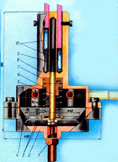
Fig. 1. 1-Nozzle, 2 - Tray, 3 - Washer, 4 - Diaphragm, 5 - Stem, 6 - Spring 7 - Bush, 8 - Housing, 9 - Magnet, 10 - Reed Switches
In the upper position the diaphragm moves under the pressure of the fuel coming from the pump, and in its lower returns coil spring 6. To activate the sensor in the fuel line has three fitting 1 (one on the pallet, and two on the body).
Hydraulic schematic diagram of the flow meter shown in Fig. 2. Through the channel 3 and the solenoid the fuel from the fuel pump enters the channels 1, 2 and fills the top and bottom of the sensor cavity and through the channel 4 enters the carburetor. Switches the valve under the influence of signals of the electronic unit (in this diagram not shown), operated reed switch sensor.
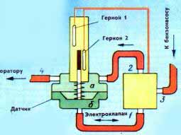
Fig. 2
In the initial state, the coil of the solenoid valve is de-energized, channel 3 communicates with the channel 1 and channel 2 peperit. The diaphragm is in its lower position, as shown in the diagram. The pump creates an excess of fluid pressure in the lower cavity 6. Develops motor fuel from the upper chamber and the sensor diaphragm will slowly rise, compressing the spring.
Upon reaching the top position will trigger the reed switch 1 and the solenoid will close the channel 3 and open the channel 2 (channel 1 is open continuously). Under the action of compressed spring diaphragm quickly moved down to its original position, and perepustit fuel through channels 1, 2 from the cavity b to a. Then the cycle of operation of the flow meter repeats.
The electronic unit (Fig.3) connected to the sensor and the solenoid valve flexible cable through the connector 1. The Committee SF1 and SF2 (1 and 2, respectively, in Fig. 2) is mounted on the sensor (in the diagram they are shown in the position when the magnet is not affected by any of them); Y1 - coil of the electromagnet of the valve. In the initial position, the transistor VT1 is closed, the contacts K1.2 the relay K1 is opened and the coil Y1 is de-energized. The sensor magnet is next to the reed switch SF2, so the switch does not conduct current.
Fig. 3
As the flow of fuel from the cavity and the sensor magnet slowly moves away from the reed switch SF2 to the reed switch SF1. At some point the switch SF2 switches, but it will not cause any changes in the block. At the end of the magnet will switch reed switch SF1 and through him and resistor R2 will flow base current of the transistor VT1. The transistor opens, will trigger the relay contacts K1 and K1.2 turn on the solenoid valve, and the contacts K1.1 closes the supply circuit of the counter pulses E1.
As a result, the diaphragm together with the magnet starts to move quickly down. At some point the switch SF1 after the reverse switch will break the circuit base current of the transistor, but it will remain open, since the base current now flows through the closed contacts of K1.1, diode VD2 and the reed switch SF2. Therefore, the stem of the diaphragm and the magnet will move. At the end of the return stroke the magnet will switch reed switch SF2, the transistor is closed, the solenoid valve Y1 and counter E1 turns off. The system will return to its original state, and a new cycle will start its work.
Thus, the counter E1 captures the number of cycles of operation of the sensor. Each cycle corresponds to a certain volume of fuel consumed, which is equal to the volume of space defined by the diaphragm in the upper and lower positions. The total fuel consumption is determined by multiplying the meter reading on the amount of fuel expended during one cycle. This amount is established by calibration of the sensor. For ease of reference spent fuel volume per cycle is chosen to be equal to 0.01 liters. If desired, this amount can be reduced or increased. It is necessary to change the distance between the reed switches in height. When the specified size of the sensor the optimal stroke of the diaphragm is equal to about 10 mm., the cycle time of the sensor depends on the mode of operation of the engine and is in the range from 6 to 30 C.
When calibration of the sensor need to disconnect the tubing from the tank car and insert it into the measuring vessel with fuel, and then start the engine and to produce a certain amount of fuel. Dividing this number by the number of cycles over the counter, get the value of a unit volume of fuel per cycle.
The flow meter there is a possibility to disable the switch SA1. In this case, the diaphragm of the sensor is always in the lower position and the fuel channels 2 and 3 through the cavity and will flow directly to the carburetor. To disable the device in the valve you need to remove the rubber sleeve that overlaps the channel 3, but it will deteriorate the accuracy of the flowmeter.
The electronic unit is mounted on a circuit Board made of fiberglass with a thickness of 1.5 mm. Drawing Board shown in Fig. 4. Parts mounted on the Board, circled in the diagram dash-dotted line. The fee is mounted in a metal box and fastened in the vehicle under the dashboard.
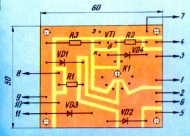
Fig. 4
In the device used in the relay RES, passport PC4.529.029.11; electrovalve - P-re 3/2,5-1112. The counter C-206 or SB-1M. The permanent magnet can be used with any end location of the poles and a length of 18 to 20 mm, it is only necessary that he moved freely in the channel without touching the walls. For example, suitable magnet from remote switch RPS, you just have to whittle down to proper size.
Case and pallet sensor turn from any petrol-non-magnetic material. The wall thickness between the channels of the reed switches and the magnet should not be more than 1 mm, the hole diameter of the magnet is 5.1+0.1 mm, depth 45 mm, the shaft is made of brass or steel 45 with a diameter of 5 mm, a length of thread - 8 mm, length - 48 mm Thread fittings on the sensor - M8, the hole diameter is 5 mm, and the fittings of the valve is tapered To 1/8" GOST 6111-52. The spring is wound from steel wire with a diameter of 0.8 mm GOST 9389-75. Spring diameter - 15 mm, pitch 5 mm, length 70 mm, the full force of compression - 300…500 g.
If the rod is made of steel, the magnet is retained therein due to the magnetic forces. If the rod is made of a nonmagnetic metal, the magnet must be glued or strengthened in any other way. To ensure that the sensor does not interfere with the compressible pressure above the magnet of the air in the sleeve should be provided with a bypass section of about 2 mm2.
The diaphragm is made of a polyethylene film having a thickness of 0.2 mm. Before installing the sensor needs to be formed. You can use the pan sensor Assembly to the connector. It is necessary to make technology fit ring from a sheet of aluminum having a thickness of 5 mm. form this ring corresponds exactly to the Assembly and the flange of the tray.
For forming the diaphragm rod Assembly from its billet insert with the inner side in the fitting hole of the tray and clamp the workpiece technological ring. Then node uniformly heated from the side of the diaphragm, holding it over the flame of the burner at a distance of 60…70 cm and slightly lifting the rod, molded diaphragm. In order that the diaphragm is not lost elasticity in the process of operation, it is necessary that it was always in the fuel. So the long-term Parking a car, you must pinch the hose from the sensor to the carburetor to prevent the evaporation of gasoline from the system.
The sensor and solenoid valve mounted on the bracket in the engine compartment near the carburetor and fuel pump and the cable is connected with the electronic unit.
The performance of the meter may be tested without installing it on the car using a pump with a pressure gauge connected instead of the fuel pump. The pressure at which the sensor triggers must be 0,1…0,15 kg/cm2. Test meter on the car "Moskvich" and "Lada" showed that the accuracy of measurement of fuel consumption does not depend on the mode of operation of the engine and is determined by the error of the unit volume at calibration that is easy to bring up to 1.5…2 %.
Author: V. Gumenyuk, Kharkov; Publication: N. Bolshakov, rf.atnn.ru