When Troubleshooting the wiring of the car often use a measuring and testing devices. This probe is a combination of the simplest indicators of voltage and resistance. Application this device offers certain advantages compared to other, as the probe is always ready for operation, charging occurs in the process work, the probe does not contain a switch, which is convenient when using it. The probe can monitor the voltage at 7...In, check out the serviceability of diodes, transistors, capacitors, TableRow, switches.
In Fig. 1 is a schematic diagram of a probe. In the "continuity" with the circuit probe illuminates the led HL1. When connected to the probe minus 1, and by the probe 2, respectively, plus the current source, the led turns on HL2. Resistor R1 is restrictive, the resistance is chosen to work with voltages up to 28 V. the LEDs HL1 - red, HL2 green.

In Fig. 2 shows a modified diagram of the probe with flashing led HL3. When the reed switch is closed, i.e. to the body of the probe presented to the magnet, the probe works in the circuit of Fig. 1. When the open reed switch probe is used as a generator signal, the probe 1 is connected to the wire that you want to ring, probe 2 is shorted to ground. On the other end is connected to the probe, the circuit which is shown in Fig. 1 (probe 2 to ground). On closing the circuit, ie. finding the right wires in the wiring, LEDs probes blink. The device is very economical, as the generator starts to work only when finding the right wires. LEDs HL1 - red, HL2 green, HL3 - red flashing.
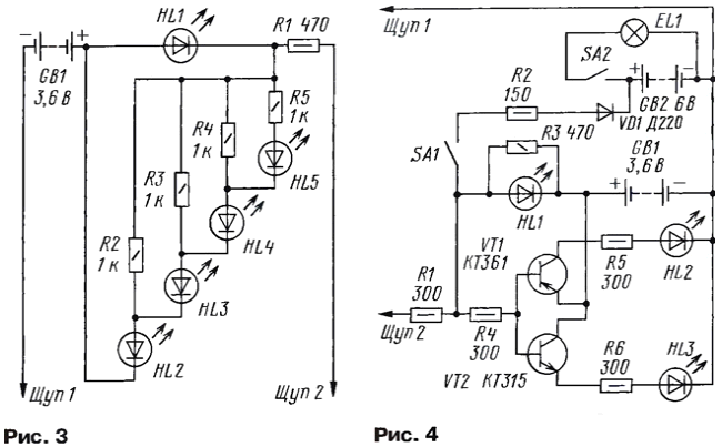
In Fig. 3 is a schematic diagram of another probe. It allows to control the voltage level. The principle of its operation is the same as in the probe according to the scheme of Fig. 1, except that depending on the voltage level of will light up a different number of LEDs. LEDs HL1 - red, HL2-HL5 green.

In Fig. 4 is a diagram of the probe, allowing to monitor the presence voltages from 2.5 V (i.e. the probe can be used to check devices for logic chips). The design includes a backlight for work in confined spaces. With the closure of the probes between the base transistor VT1 is served minus, it opens and the led turns on HL2. Probe 1 connected to the case. If the probe 2 to apply a voltage of about 2...3, opens the transistor VT2 and the led lights up HL3. If you increase the voltage until about 6...7 In, the led will light HL1, the transistor VT2 is still open and the HL3 led will be steady on. Resistor R4 determines the threshold of discovery transistor VT1. Charging the battery the backlight is through a current limiting resistor R2 and the diode VD1, when the circuit SA1.
LEDs HL2 - red, HL1, HL3 - green.
Resistors R1 - R5 - MLT-0,25. LEDs HL1 - HL5 recommend type MIDH-40, but you can use any other (in the scheme in Fig. 2 HL3 - any flashing the led). Transistors VT1 - series KT361, VT2 series KT315 or the like, VD1 - any diode current from 0,26 A. GB1 - battery of three elements. The batteries I recommend hearing AIDS capacity 0.03-h, but you can use any other. GB2 - battery, composed of the five elements, the capacity of 0.26 A-h or the like. The probe 1 is made wire clamp type "crocodile" at the end. Probe 2 - needle, made of straightened and sharpened piece of the spring to be able to disassemble automotive connectors. Samples collected mounted Assembly, checked them operability. Then they are placed in the form of clay or cardboard and are filled with epoxy resin. After hardening of the resin the probe is processed with a file. To charge the battery tester included in the circuit to measure voltage.
Author: A. Medvedev, Yaroslavl


