The scheme is designed to protect against inrush current charge when switched on uncharged capacitor in on-Board network. Who has not tried to enable the uncharged in poradnik network without a limiting resistor "I think not... at least, will burn the contacts.

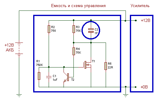
When you turn discharged capacity in the network, the capacitance C1 is discharged, T1 (n-MOS low-key the resistance of the channel) is closed. The capacitance C2 (the same poradnik) charged via low-resistance R5. T2 opens almost instantly, open land C1 and the gate of T1. When the potential is negative terminals C2 falls below 1V (charge to Uакб - 1B), T2 is closed, C1 smoothly charged to about 9/10 of Uакб, opening T1. The time constant R2C1 quite large, so the jump current T1 (recharging C2 +1V to the Uaкб) not more than the T1.
In further negative terminal C2 is continuously shorted to earth via T1, REGARDLESS The direction of the CURRENT in T1 (as in direct - from drain to source, and in return direction). Nothing wrong with "turning" OPEN A mos transistor is not. When choosing well enough of the conductive transistor entire reverse current will flow through the channel, and the built-in reverse diode will not open, as the voltage drop across the channel at times less required to open 0.5-0.8 Q. by the Way, there is a whole class TIR devices (so-called FETKY) intended to work in reverse direction (synchronous rectifiers), they have a built-in diode shunted additional power Schottky diode.
Calculation: for the transistor IRF1010 (Rds=0.012 Ohms), the voltage drop of 0.5 Ohms will achieved only if the current channel 40A (P=20W). For four of these transistors in parallel and the same the discharge current of 40A on each the transistor will dissipate 0.012*(40/4)^2 = 1.2 W, i.e. radiators not 'll need (especially as 1.2 W will dissipate only when differential current consumption but not constantly).
With dense installation (You have a lot room for another radiator?) - it is expedient want to parallel small-sized (body TO251, DIP4) transistors, in General not providing radiators, based on the ratio of current(power) consumption of the amplifier - Rds - maximum dissipated power. Because Pds max is usually equal to 1W (800 mW for DIP4), the number n transistors (c Rds each) amplifier output power pout must be at least n > 1/6 * Pout * sqrt(Rds) with 12V power (the dimension in the formula I have omitted). In fact, taking into account the short duration of current pulses, n you can safely reduce by half compared with this formula.
The charge resistor R5 is selected from compromise thermal power and charge time. Under these 22 Ohm - the charging time is about 1 minute at the dissipated power 7 watts. Can instead of R5 include a 12V light bulb say, from the turn signal. The Resistors R1, R3 - reinsurance (drain capacity when disconnected from the network).
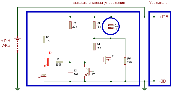
For activation plug additional inverter (slimming R2). Attention! The scheme is efficient when the use of n-p-n transistors T2, T3 with h21e > 200 (KT3102). Depending on the brightness of LEDs, R1 selectable in the range of 200 Ohm - 1K.

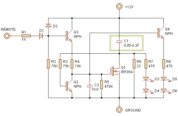
But the option scheme, in which the shutter key is controlled by the signal REMOTE (transistor). When unconnected or off REMOTE the key transistor guaranteed to be closed. LEDs D3-D4 indicate charging C1, D5-D6 - an open state of the key.

Accurate indication of the threshold voltage easiest way provides IC TL431 (CREN) typical comparator voltage (with appropriate a divider in the input circuit and current limiting R in the circuit of the cathode).
Loss schemes largely depend on installation. It is necessary to ensure minimum resistance (and relevant to the current thickness wires) to power circuit (terminal + / S2 / T1/ terminal). In Amateur practice, I think, to do external terminals impractical - better immediately to unsolder the short AWG8 wire, which scheme is bound to the terminal of the amplifier.
Publication: www.klausmobile.narod.ru, www.cxem.net


