


")

Cars of the early years of production, as it is known, provides a smooth regulating the duration of pauses between the working stroke of the wiper blades in intermittent, but on some machines instead of the intermittent mode is applied slow stroke brushes. Therefore, if your car is out of order the wiper switch or ceased to hold you, you to collect more perfect device described in this article.
Questions of the design and operation of automotive wiper Amateurs pay a lot of attention - just finished devices for twenty in recent years the journal has published about a dozen (for example, [1-7]). As shown practice, the most stable temporal characteristics of the cycle of movement of the brushes provided those collected on digital circuits.
According to the analysis published switches was developed and tested in operation construction collected on digital circuits, in which there is the opportunity to refuse timing capacitor oxide. Switch designed for installation in automobiles VAZ-2103, 2106 instead of relay wiper, but can also be applied in other models of the series of vases. In a slightly modified form of the switch is suitable for GAZ-24 and "Moskvich-2140".
Diagram of the device depicted in Fig. 1. It consists of driver time intervals with adjustable duration, assembled on the counter - oscillator DD2, shaper group of cycles of brushes when you first switch wiper the element DD1.4, the capacitor C3 and the resistor R4. The drive motor M1 turn on the SCR VS1, a controlled current amplifier transistor VT1.
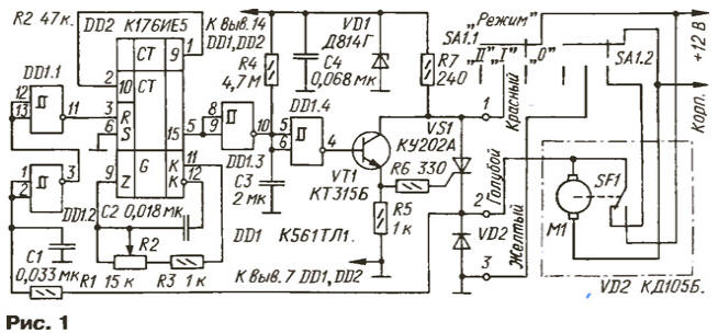
The switch is connected to the electrical system of the vehicle in accordance with the specified color designation wires. Available car relay wiper removed.
In the initial position of the mode switch wiper power the switch is not supplied. When the switch is in position "I" at line 1 received the vehicle voltage, and the wire 3 is connected to the body. As at the time of inclusion on the upper circuit on the output capacitor C3 voltage close to zero, the output of the Schmitt trigger DD1.4 to the base of transistor VT1 will go the voltage is high, which will open the transistor VT1, and turn - SCR VS1.
The wiper motor will receive power supply voltage, and it will start to work.
At the same time through a smoothing circuit R1C1 and the Schmitt trigger DD1.1 and DD1.2, performing the role of buffer elements, voltage high-level the motor will go to the reset input of one of the counters chips and DD2 will keep the counters in the zero state (low level at the output 15). When each switching of the movable contact of a limit switch SF1 drive wiper on the right on the diagram the position of the SCR VS1 will be closed, and when returning to the previous position again be opened until the capacitor C3 is not charged through the resistor R4 to the threshold voltage trigger DD1.4. This will happen in 5, 7, during which the brushes will make some continuous moves.
After switching trigger DD1.4 at its output appears low, as the output element DD1.3 - high. Transistor VT1 is closed and the next the return of the movable contact end of the switch SCR will remain VS1 closed, the wipers work in continuous mode will stop.
When you stop the engine inlet R chip DD2 appears low and the counters begin counting pulses generated by the generator section of this of the chip. The oscillation frequency can be adjusted by the variable resistor R2.
When the number counted by the pulse counter reaches 214, the output 15 the counter will appear a high level. The low level output of the inverter DD1.3 will switch the trigger DD1.4 in one state. Transistor VT1 is opened and will include SCR VS1 - motor will start to work. As soon as the movable the contact end of the switch will move to the right, closes SCR VS1, and the input R of the counter chip DD2 will reappear high level, which will reset the counters. Wiper blades will make one working cycle and stop.
Then DD2 counter again starts counting pulses and the process repeats itself. The wiper will operate in intermittent mode. Changing the resistance variable resistor R2 from zero to maximum, you can change the pause time between the working strokes of brushes from 0.5 to 20…25 C.
Use the switch chip CIE allowed to use for the job periods of time, the capacitor C2 of small capacity, which increased the reliability and the stability of the device. Diode VD2 suppresses the voltage pulses of opposite polarity in the circuit R1C1. In addition, it increases the immunity of SCR (without diode when returning the movable contact of a limit switch SF1 SCR re-opened). Since the voltage in the vehicle electrical system sometimes (during fault) to exceed 15 In, to protect the Zener diode VD1 with the ballast resistor R7.
Chip CTL in the switch can be replaced by imported or IW4093BN CLA, CTL, CLA (the use of the Schmitt trigger is preferable). Transistor - any low-power silicon, the structure of the n-p-n. SCR is suitable any of the series KU, KU. The Zener - voltage stabilization 10…12 V; also mentioned in the scheme, suitable DW, DD, XA, XB, XE. Diode VD2 - any of the series KD, KD, KD, KD, KD.
The capacitors should be selected from the series K73-9, K73-5, K73-11 and the Condenser. C3 should have a small leakage current, therefore, the oxide is better not to apply. Variable resistor R2 may be any resistance from 22 to 100 ohms, you only want to save the limits of the adjustment of the duration of the pause button the product C2 (R2+R3) remained close to 18x48x10 C. the R2 Resistor (47 kω) it is advisable to choose from the group B or that the scale of the restructuring was close to linear.
When installing the switch on a GAZ-24 or M-2140, it is necessary make small changes, since the connection diagram of the motor the wipers of these machines differs from the VAZ (Fig. 2).
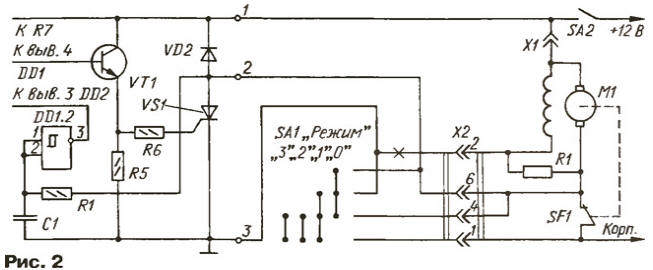
As can be seen from drawing, SCR VS1 and the diode VD2 need to swap the trigger DD1.1 remains free. The output signal of the inverter DD1.2 goes directly to the input R of the counter. Modifications required in the circuit diagram of the car shown in the snippet the schema. The cross marked the conductor that you want to delete ("break").
With this inclusion in the "1" position of the switch SA1 "Mode" instead of quiet progress will be intermittent work continuously adjustable time pauses. In positions "2" and "3" switch is de-energized, the wiper operates in the mode prescribed plant.
All parts of the device except the variable resistor R2 is placed on the printed Board of foiled fiberglass 1.5 mm thick. a Drawing Board is depicted in Fig. 3. The topology of the conductors on the circuit Board is made to it was possible to collect both options of the switch. The corresponding changes in the installation Board implement the jumper settings of flexible insulated wire and the cutting of printed conductors.
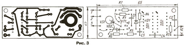
Cost is attached near the variable resistor R2, the handle of which has been brought to the panel devices in a convenient location.
Establishing a switch is not required. If you want to change the time of continuous the brushes work when you first start, choose a resistor R4. The limits of regulation time pauses you can change the selection of the capacitor C2.
Literature
Author: I. Potechin, Fokino Bryansk region.