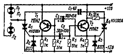
Contactless alarm relay turns the car can be constructed using silicon controlled diodes - thyristors. The scheme of such a relay is shown in the figure.
The relay is a conventional multivibrator transistors T1 and T2, the switching frequency which determines the frequency of the flashing lights as the multivibrator controls the switch of the DC power thyristors D1 and D4.

In the multivibrator can work any low-frequency transistors.
When connecting the switch L1 signal bulbs front and rear sidelights signal of the multivibrator opens the thyristor D1 and the battery voltage is applied to the signal lamps. In this case, the right plate of capacitor C1 is charged positively (relative to the left electrode) through the resistor R5. When the starting pulse of the multivibrator is fed to the thyristor D4, this thyristor is opened and the charged capacitor C1 is connected to the thyristor D1 so that he instantly gets a reverse voltage between the anode and the cathode. This reverse voltage closes the thyristor D1, which interrupts the current in the load.
The next pulse of the multivibrator again opens the thyristor D1 and the whole process repeats. Diodes D applied to limit negative current emissions and improve thyristor triggering.
In the switch of the DC can be applied to any low-power thyristors with any alphabetic indices. When using thyristors QUA the current consumed by the signal lamps shall not exceed 2 a; for thyristors KUA it can reach up to 10 A.
The relay can operate from the on-Board network voltage of 6 V.
Author: A. Stakhov, Kazan; Publication: N. Bolshakov, rf.atnn.ru


