


")

As you know, back brake signal light domestic cars Shine constantly, as long as you press the brake pedal. In recent times can meet machine, which when braking with lights brake include additional signal lights, intermittent glow, besides sometimes movable in form and location.
The specialists of the traffic police is considered appropriate from the point of view of increasing the security motion installation of duplicating flashing brake signal lights, it is only necessary to avoid the "illuminative" excesses. A few years ago the domestic industry produced extra lights brake equipped the simplest electronic switch current. They were supposed to be mounted behind the rear the glass partition and connect in parallel to the main chain of the lamps. When you click on the brake pedal extra lights blinking red light.
Below describes a simple circuit breaker for auxiliary lights (see diagram on Fig. 1) working on a particular algorithm. The device is assembled on two popular and inexpensive CMOS chips and two transistors. To connect the device can only parallel to the lamps stop lamp. Any other option connect additional lights are dangerous because when random faults switch main stop signals may be de-energized, causing the danger of rear-end collisions, especially in the dark, is increasing dramatically.
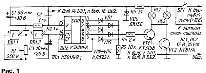
On the elements of DD1.1, DD1.2 assembled pulser working at a frequency of 4 Hz. The pulses arrive at the counting input of the decimal counter DD2. As to the enable input of the account CP first low level is applied, the expense occurs at the positive differential voltage at the counting input.
When the supply voltage of the high level pulse from resistor R2 sets the counter to its initial state. Then the outputs of the counter alternately you receive a high level pulse. Once a high level will appear on the outlet 8, the account is terminated and the counter remains fixed in this state until the brake pedal is released and the switch node.
The counter outputs are connected integral with the base of the output transistor node VT1VT2 OR collected by the diodes VD1-VD5 and resistor R3. The load of the output transistor serve two car lamp lights HL1, HL2.
While the outputs of the counter pulses appear alternately high level, opening a composite transistor, the lamp flashes synchronously with the pulses. Since the counter is not used, all outputs, but only every second, between the lamp flashes a pause of the same duration.
Therefore, each time you press on the brake pedal lamp flashes four times with a frequency of 4 Hz, and then turn on continuously until the switch switch. The frequency of outbreaks can to some extent modify trimmer resistor R1.
The Zener diode VD6 and capacitor C1 together with the resistor R5 protect the device surge on-Board network and impulse noise in the power supply circuit. In normal operation, the Zener diode is closed and the work does not participate.
The device is assembled on a printed circuit Board of foiled fiberglass 1 mm-thick Drawing Board depicted in Fig. 2. Power transistor VT2 in the heat sink is not needed. Fee set in a sturdy plastic box, mounted in a convenient location in the trunk.
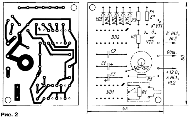
The condenser C3 - K53-4; fit and any other oxide capacitor with minimal dependence of capacitance on temperature. Capacitor C1 - K53-18, C2 - low-voltage K73-17A. The trimmer R1 - SDR-6A.
Establishing a switch is not required. If you do not want to change the flashing frequency additional lights that is better trimmer set constant in the same resistance.
Switch and extra lights can be installed on cars with the Board voltage of 24 V. In this case, the gap plus the wire between the resistor R5 and the point of connection of lamps HL1, HL2 need to install chip-stabilizer CREB or CRED, she has the input - output 17(1), the output - 2 (3), 8(2). The output of the current amplifier should be selected transistors with a voltage collector-emitter not less than 50 V. for this Lamp option switch will need dvadtsatichetyrehletnem.
Too powerful lamps to further lamps should not be applied so as not overload contacts the brake light switch.
The switch will work better if, instead of polar capacitor C3 to install non-polar at the same capacity and voltage.
Author: A. Kashkarov, St. Petersburg