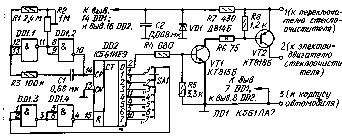
Simple electronic unit, which I propose adding machine Ulyanovsk automobile plant, will improve the management of the wiper. Although the device was designed for cars UAZ, it can be used on the "Lada" to replace the failed built-in Electromechanical controller.

Node circuit shown in Fig. 1. Logic elements DD1.1, DD1.2 is formed of a low-frequency square-wave generator, which is input to the counter DD2. Transistors VT1, VT2 assembled the current amplifier. The transistors work in switching mode.
When the output of counter 0 high level opens the transistor VT1 and followed him VT2 - activated wiper motor. After some time, the high level at the output of counter 0 is replaced by a low, transistors are closed and the motor is disabled and the counter continues to count.
Once a high level appears at the output of 1 meter, this level after a double inversion elements DD1.3, DD1.4 will reset the counter and start a new cycle of counting impulses. If the switch SA1 switch in position with a larger number, the time of resetting the counter will be at a later time, i.e. the pause between successive inclusions wiper will increase. In position "1" pause practically absent.
A trimming resistor R2 sets the desired frequency of the generator, and hence the wiper motor in each cycle. On
the resistor R7 and Zener diode VD1 is assembled parametric stabilizer for power circuits.
All elements of the site, in addition to the transistor VT2 and the switch SA1, mounted on a printed circuit Board of foiled fiberglass 1.5 mm thick. The drawing Board is presented in Fig. 2.
Pads 1 - 7 and U posted on the Board from the printed conductors near the place of installation of the chip DD2, are designed for connection with the switch SA1. It is mounted near the windshield wiper. If you do not want such a wide selection of the length of the pause, you can use the switch SA1 to fewer regulations.
For one of the selected values of the length of the pause switch is not needed; only the pad P to connect the jumper with a corresponding output of the counter. Suppose, for example, the selected output 7 - then in each cycle brushes will do three double stroke on the glass, and the pause will be equal to 5...7 p.
The transistor VT2 can be screwed to a small heat sink in the form of a plate sizes HH mm aluminum. The heat sink on the four pillars are fixed parallel to the Board.
All resistors site, in addition to R2 and R6, - MLT-0,125. Resistor R6 must have a power dissipation of at least 2 watts. Trimmer resistor R2 may be of any type, better closed design, and fixation of the shaft. Capacitors - KLS or km. The Zener diode VD2 can be at any voltage 8...10 V, preferably miniature. Instead of the transistor CTB will fit any of the series KT815, CT, and instead CTB-any of a series of CT.
Mounted charge is placed in the box for the relay mku-48 and fixed under the dashboard of the car.
On connecting the node to the electrical system of the vehicle UAZ-3151. Of the six colored conclusions switch wiper use three green connect the positive to the positive wire of the vehicle, a gray - to pin 1 of the Board, and white with the pin 2 and the electric motor. The other three output left free. Conclusion 3 the Board is connected to the vehicle body.
When such a connection is in the leftmost position of the wiper switch is turned off, in the middle position - continuous operation of the brushes, in the right - intermittent.
When installing the hub on the car "Lada" is available Electromechanical output Board 1 is connected to a red wire, 2 - blue, 3 - yellow. The mode of operation of the wiper in this case will change somewhat. Now in each cycle of the brush will be depending on the position of the engine of the resistor R2 to make 2-3 double stroke with a pause at 2...13 set by the switch SA1.
Operation of the described node on the UAZ-3151 showed good results. The lack of capacitors contributes to the reliable operation of the node.
Author: A. Petukhov, Biysk, Altai Krai; Publication: N. Bolshakov, rf.atnn.ru


