


")

Modern vehicles are equipped with a large number of electronic devices: switches ignition system, controls the operation of the engine, diagnostics, onboard computers of it. D. some of these devices, installed on domestic cars VAZ and GAZ, we will introduce our the readers. This information can be useful both to experts, tech and fans, involved in the repair of such equipment. Today we will focus on the display unit bortai control system.
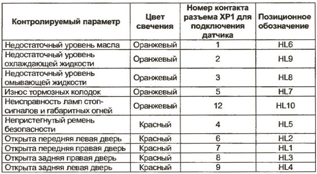
The display unit onboard control system (BI BSK-10, next - block) is designed to display the status of units of the car with ten and one light audible alarms. The list of monitored parameters and color respective light signals shown in the table.
This device with the notation 12.3860 and installed on all 2110-3860010-04 modifying cars VAZ-2110 [1]. Described here is a variant of the block produced with little change from 1998 to 2002.
Operating unit can be in one of five modes:
1. "Off" - a missing key in the ignition.
2. "Waiting" is the key in the ignition in the off position. If driving the door is open, the unit records the event "the forgotten key in the ignition and beeps for 6 p.
3. "Predvestnik control switches" - when turning the key to position "ignition". Length mode 4 C. the beep will sound one, and all light indicators turn on at 4 C. the control fault "lack of oil", "insufficient coolant level", "lack of washer fluid", and the value of them to remember, however, light signals are not included until the end of the regime.
4. "Predvestnik control settings" at the end of the mode control predvestnik alerter" and pause at 1 C. the Duration of the mode - 6 S. Triggered the lights blink first for 6 with a frequency of 1 Hz, then glow constantly until the failure or turning the key to position "off". The beeper is switched on simultaneously with light signals at 3 p.
Registered malfunction "lack of oil", "insufficient the coolant level, lack of washer fluid", "fault lamps stop lamps and tail light and brake wear pads memorized before turning the key in the off position.
5. "Control parameters when the engine is running" starts at the end of the regime "predvestnik control parameters". Stop fault monitoring "lack of oil", "insufficient coolant level", "lack of washer fluid", fault monitoring "unclosed door", "seat belts", "fault lamps stop lamps and tail light, brake pad wear" continues.
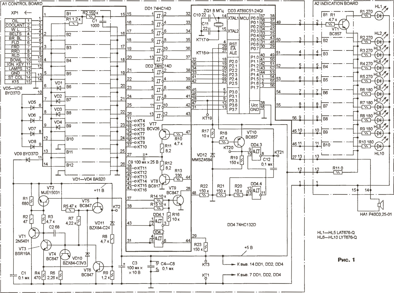
The device consists of two main parts (Fig. 1): microprocessor and indicator, mounted on the control Board A1 and on-Board display unit A2, respectively. Both boards are installed in a plastic housing.
(click to enlarge)
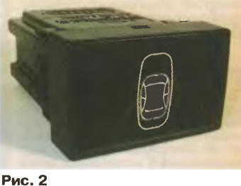
The appearance of the block shown in Fig. 2. To connect power and sensors uses a 15-pin connector.
The output signals of the transducers come with the connector pins HR the inputs P0.0-P0.5, P2.0-P2.5 microcontroller DD3 through matching circuit AV-AV and triggers Schmitt DD1, DD2 [2]. The Outputs P1.0-P1.7, P3.1, P3.2 is a microcontroller designed to control transistor AV-AV, which, in turn, commute LEDs HL1 - HL10. To produce the sound signal, simulating a bell, is the dynamic head HA1, which connected through a coupling capacitor C9 to the output of the amplifier transistor VT7, VT8, controlled by the outputs of RZ.b, P3.7 microcontroller DD3.
When the key is in the ignition lock of the vehicle, the power supply voltage is supplied from the pin 11 of connector HR through the diode VD9, which protects the unit against reverse polarity, on the voltage regulator, transistors VT1-VT6. Chain VD11R8R9VT6 turns off the power to the unit when the voltage exceeds 24 Q. the Stabilizer provides the minimum voltage drop (not more than 0.6 In under full load) and allows flow pulse input voltage up to 150 V.
The microcontroller DD3 [3] contains a built-in clock oscillator running external ceramic resonator CSA-8.0 MTZ company Matanag.
The reset signal for a fixed time for the microcontroller DD3 after the filing the voltage supply or in the case of a decrease below 4.2 develops In the node ("the supervisor"), consisting of a threshold element transistor VT10, the Zener VD12 and the single vibrator on the elements DD4.3, DD4.4. In standby mode (ignition off, all doors closed) the chip DD3 is "sleep" state, the current consumed by the unit, does not exceed 7.5 mA. If the key in the lock to position "ignition" or open any front door, the node on the element DD4.1 and the transistor VT9 generates an interrupt (the log. 0) on the output RZ.W microcontroller DD3, deducing it from "sleeping" state.
Block indicates the open state of each door of the vehicle. To save individual signals from each door switch and turn the light on in the cabin when opening any door, applied to the diodes VD5-VD8. Diodes VD1-VD4 prevent the supply of power to the unit through the lamp, interior lighting car.
In block mainly applied elements for surface mounting. Capacitor C9 - aluminum oxide SKR101M1EE11VM JAMICON company (may substitute for similar), the condenser C3 - tantalum size D for surface mounting, all other capacitors and resistors sizes 0603, 0805 and 1206. Transistors and MJE15031 2N5401 can be replaced by CTA and CTA, and the transistors US and WS - CTA-9-CTG-9 and CTU-9-CTD-9, respectively.
Codes of the firmware of microcontroller AT89C51-24QI (DD3)
Literature
Author: A. yuferov, Cheboksary