


")

The application of a trigger device will be particularly useful to motorists, engaged in the operation of the car in the winter time, as it prolongs the life of the battery, and also allows you to have cold car in the winter, even with a fully charged battery. From experience shows that in sub-zero temperatures the battery reduces its impact on 25…40%. And if it is not fully charged, you will not be able to provide the required to start the motor primary current of 200 A. This current is consumed by the starter to start the time of the spin-up motor shaft (nominal current consumption by about 80 starter But at the time of launch it much more).
Simple calculations show that, in order for the launcher worked effectively when you connect it in parallel with the battery, it should to provide a current of at least 100 And at a voltage of 10…14 V. the nominal the capacity of the network transformer T1 (Fig. 4.1) should not be less than 800 watts. As is known, the nominal operating power of the transformer depends from the sectional area of the magnetic core (iron) in the location of the windings.
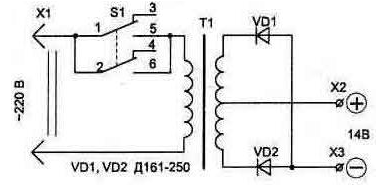
Fig. 4.1
The scheme itself is a trigger device is quite simple, but requires the right the manufacture of the mains transformer. For it is convenient to use a toroidal iron from any LATRI - with minimal dimensions and weight in the device. The perimeter of the cross section of iron may be from 230 to 280 mm (different types autotransformers it differs).
Before winding coils must be rounded with a file the sharp edges on the faces the magnetic core, after which it is winding varnished cloth or fiberglass.
The primary winding of the transformer contains approximately 260 290…turns of wire sew-2 with a diameter of 1.5 to 2.0 mm (wire can be any type of varnish insulation). Winding distributed evenly in three layers with interlayer insulation. After the initial winding, the transformer must be included in the network and to measure the load current. It needs to be 200…380 mA. This will optimal conditions transformation of power to the secondary circuit. If the current is less, the portion of the turns need to rewind, if more - domotat to obtain a specified value. However, note that the dependence between inductive resistance (and hence the current in the primary winding) and the number turns is a quadratic - even a slight change in the number of turns will be to result in a material change in the current of the primary winding.
The transformer in the idle should not be heating. Heating coil indicates the presence of interturn fault or burst and circuit part winding through the magnetic core. In this case, the winding will have to do again.
The secondary winding is wound insulated stranded copper wire cross section of at least 6 mm2 (for example type. ПВSW with rubber insulation) and contains two windings 15…18 turns. Wound secondary winding at the same time (two wires) that makes it easy to get their symmetry - the same voltage in both windings, which should be in the range of 13.8 V 12… at rated mains voltage of 220 V. Measure the voltage in the secondary the winding is better to temporarily connected to the terminals x2, X3 load resistor resistance 5…10 Ohms.
The diagram shows the connection of the rectifier diodes allows you to use metal parts of the launcher, not only for fixing diodes, but also as a heat sink without dielectric spacers (plus diode is connected with a fixing nut).
To connect launchers parallel with the battery, connecting the wires must be isolated and stranded (better if copper), with cross section of at least 10 mm2 (not to be confused with the diameter). On the ends of the wire after tinning, with terminals soldered.
The contacts of the switch S1 must be rated for a current of less than 5 A.
Author: I. P. Shelestov