


")

This device is designed to maintain the diesel engine car warmed in the cold season in the absence of its owner. Many owners of such cars had to deal with the problem of starting diesel engines in cold days that usually associated with a fairly high value of the freezing point common brands of diesel fuel.
The luxury car models are equipped with a special automatic system easily start and warm up the diesel engine at a specified time or a specified time intervals. Building on this idea, I developed a device that using the specified intervals launches diesel, gives it to work some time off. Machine-heater was manufactured in several copies and have shown reliable operation. In particular, for three winters he successfully operated by car "Ford Transit".
The machine is a timer with the Executive nodes operating in the following mode: a two-hour pause, then turn on the ignition after 6 to 8… with necessary for the warming glow of the candles, turn on the starter motor start; he works for 7 or 15 min, after which the ignition switched off, the motor stops and follows a new two-hour pause.
The device is mounted on the vehicle and is powered by the onboard supply voltage 12 In; the current consumed during a two-hour pause, no more than 200 mA.
Most diesel engines are equipped with a special glow candles intended for heating fuel and mounted in the cylinders (one per cylinder), or a single candle on the intake pipe. To run in the winter modern diesel engine, first turn on the ignition occurs the opening of the electromagnetic valve of the fuel pump. Further, depending on how to enable the intensity of intelligent candles, you have two options:
1. After switching on the ignition voltage is supplied to relay thermocontact control of incandescent candles. If the fuel temperature is too low, the relay and the inclusion of candles. After warming up the fuel relay disables candles, i.e. after switching on the ignition, it is necessary to pause 2 8 C to… turn off pilot lights and turn on starter.
2. Control relay candles and, thus, do include special candles button, placed on the dashboard. The relay is switched on only after switching on the ignition. Turn off the candles the same relay by thermocontact sensor after warming up the fuel or the button is released. In short, after switching on the ignition, push the button and pauses (the same 2…8 (C) to turn off warning lights.
Now include the starter, and if the engine is in good working order and properly adjusted, after a few revolutions of the crankshaft is run and work on sustainable speed.
For machine-heater driver must turn on the power in the embodiment 2 to the power of candles (to close the contacts button). Everything else are automated. If the button is held down, you need in parallel with the contacts to connect the switch and set it in a convenient location.
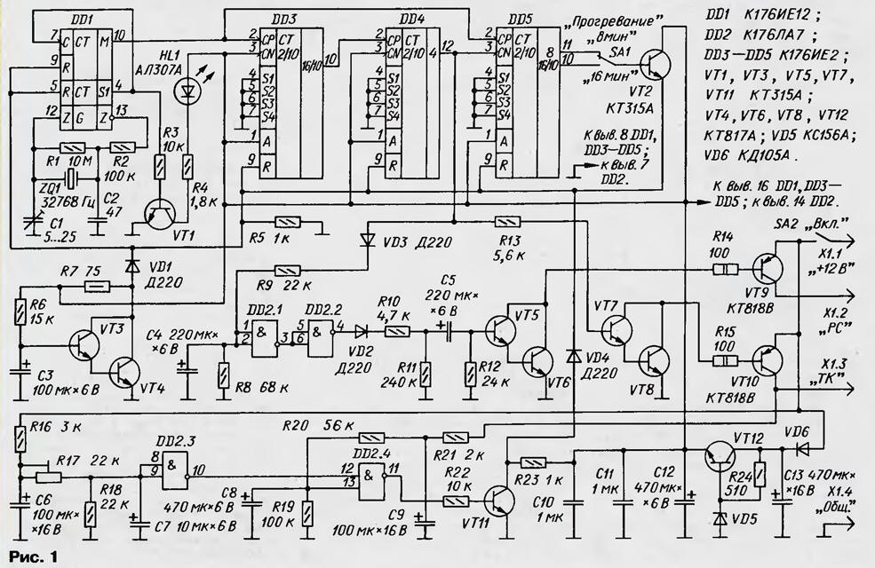
After turning on the power toggle switch SA2 (see scheme in Fig. 1) charging begins capacitor C3 voltage 5 V regulator from VT12VD5R24 through a resistor R6. On the closed manifold composite transistor VT3VT4 voltage is present 5 In that causes a reset of all counters DD1, DD3-DD5 input after About R. 0.5 the capacitor is charged, a composite transistor VT3VT4 will open, allowing work counters.
(click to enlarge)
On DD1 chip assembled a master clock, minute pulse, whose frequency stable quartz resonator ZQ1. These pulses arrive at the input frequency divider performed on the counters DD3, DD4. After 2 h after inclusion the device at the output 4 of the counter DD4 appears high level opening the transistor VT7, VT8, VT10. The 12V goes to the output TC (fuel valve) machine, which corresponds to the ignition.
The high level output from the 4 meter DD4 passes through the circuit and charges VD3R9 the capacitor C4. The node that performed on the elements of DD2.1, DD2.2, provides a time delay of 6 s, necessary for heating the glow of candles. Through the specified time, the high level from the output of the element DD2.2 through a chain VD2R10C5 is supplied to the base of the composite transistor VT5VT6, with the result that he open, opening and VT9. Now the voltage of 12 V appears at the output of the PC (starter relay), which corresponds to turning the key in the ignition to position "Starter".
Since then, the starter begins to rotate the crankshaft of the engine. At the same time begins charging the capacitor C5, which lasts about 5…6 C, after which transistors VT5, VT6, VT9 will close and shut off the starter relay. This time enough to run a serviceable engine.
Element DD2.3 monitors the voltage in the vehicle electrical system. On this level parameter host determines start the engine or not. This site, though requires fine adjustment, but the most simple.
Immediately after powering on the inputs of the element DD2.3 set low level (since the capacitors C6 and C7 is discharged), and the output is high. On the lower circuit on the input of the DD2.4 - low level (as in the first moment the capacitor C8 is discharged), therefore, the output of this element is high level, causing the transistor VT11 is open and the diode VD4 closed.
At the time of opening of the transistor VT10 (ignition on), the capacitor C8 discharged, the output element DD2.4 remains low and the diode VD4 also remains closed. Further, the capacitor C8 is charged, but the element DD2.4 will be able to switch only when the top input high level, and the voltage across the capacitor C8 reaches 2.5 V or more. This requires period of time of about 10 s, the end of which the engine should already work.
When the engine starts, the voltage increases to 14.5-15 V. Increases the voltage on the input element DD2.3, a high level at its the output gives way to low, causing the element state DD2.4 does not change.
If the engine does not start or starts and stops, it means that the voltage in onboard network decreased to 13.5…12.5 V depending on the state of charge the battery of accumulators. At the outlet of the element DD2.3 and the upper circuit the input element DD2.4 shows a high level at the lower input of the DD2.4 - too high level. As a result, the output element DD2.4 will be low level, the transistor VT11 is closed and the diode VD4 appears that, in turn, will reset the counter DD1, DD3-DD5, closing transistor and VT10 emergency switching off the ignition. This prevents the situation where the engine is not running and the ignition is on.
Simultaneously with the opening of transistor VT7, VT8, VT10 high level output 4 counter DD4 is input to the CN counter DD5 and permits the minute account the pulses. Switch SA1 select count their number is 8 or 16. So by the way, depending on the position of switch contacts SA1, using 8 or 16 min high level will open the transistor VT2 and it will reset the counter, E. switching off the ignition and stop the engine. The pulse width reset very small (less than 1 μs). Immediately after it begins a new counting minutes pulse counters, DD3, DD4, and after 2 h all of the above processes again.
Resistor R17 set the threshold voltage of the onboard network, wherein switch element DD2.3.
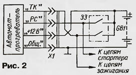
The scheme of connection of the machine to the vehicle's electrical system shown in Fig. 2 (ZZ - ignition switch; GB1 - battery).
Almost all parts of the machine are mounted on a printed circuit Board placed in the plastic case. Connect the device to the vehicle's four-way cable plug socket which is mounted near the ignition switch. Length cable should allow you to put the machine in the front seat of the car.
The capacitor C1 is any ceramic trimmer, C2 - ceramic or mica, C10, C11 - ceramic or metalloboranes, the remaining oxide C50-35. Chip CLA can be replaced by CLA. The main requirement for transistors - static current transfer ratio not less than 50. Transistors KT315, CT can be used with any alphabetic indices. Instead CTV other power transistors p-n-p with the current transfer ratio is not less than 50.
Since power transistors VT9, VT10 operate in a switch mode, and low ambient temperatures, it is enough to set them on the heatsinks with an area of 5 cm2 each.
Diodes D other interchangeable for maximum current less than 20 mA. Instead led ALA any other suitable, you just have to pick up resistor R4.
To establish the first machine temporarily connect the input of SR counters DD3 and DD5 to the output S1 of the chip DD1, i.e. instead of minute pulses to the inputs of counters serves seconds. To control more convenient to use an oscilloscope, but you can to do conventional AVO meter. The switch SA1 is set to "16 min".
After turning on the power supply (12… 13 In), checks for the presence of minute pulses at the output M chip DD1 and second output S1. Next, check the water meter DD3-DD5, which cut off the base of transistor VT2. When they are working correctly after about 2 min at the output 4 of the counter DD4 should receive the high level, and through 16C - outlet 16/10 counter DD5. After checking the output base transistor VT2 soldered into place.
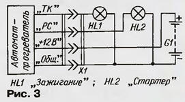
Then connect to the machine two warning lights HL1 and HL2 (Fig. 3) simulating the load and indicating the start of car parts (G1 - any source supply voltage of 14 V and a current of 2…3 (A), and verify the correct operation of the device in General. Selection of capacitors C4 and C5 are used to set the working time and delay the starter.
Final laboratory operation - adjusting tripping the ignition. The machine serves adjustable in the range 12…15 V voltage power. Increasing the supply voltage from 13, set by resistor R17 ensure that when element 14 In DD2.3 switched to 0.
Further, the machine is mounted on the car and re-check the work in the position "16 min" switch SA1. After power must follow temporary extract 2 min, then the ignition is switched on. 6 is included with the starter, the engine is started, even after 3…4 off with the ignition and the engine stops. If necessary, adjust the site emergency shutdown. After all of these operations to restore the input counters DD3, DD5 to the exit M counter DD1.
I conclude with some recommendations on the operation of the device. Those who will want to repeat this design, it is necessary to clearly understand that before to enable the machine must be shut down in the car with all appliances, box gear to put in the neutral position, tighten the hand brake, or turn the pads under the wheels. On the exhaust pipe will have to wear hose and print free its end out. Neighbors in the garage need to inform about installing on your car machine-heater.
Author: A. Dubrovsky, Novopolotsk, Belarus