


")

This control system is includes fuel pump, regulator fuel pressure, air mass meter air with a heating element, injectors, throttle position sensor valve, idle control, sensor coolant temperature and knock sensor, speed sensor of the engine, vent valve fuel tank, the canister, gauge contents of oxygen in exhaust gas (lambda probe), coil the ignition and the electronic control unit (ECU). Compared to previous models "Motronic", this control system is more perfect. Each the nozzle has a separate control channel ECU that provides high precision fuel metering and faster response to a change of the engine load. In addition, the fuel injection is performed three times in one turn of the crankshaft of the engine.
In "Motronic 3.1" already entered mass meter air a heating element that facilitates a more accurate calculation the amount of fuel the ECU. The principle of operation of the system the following. Fuel pump through a fine filter delivers fuel at the dispenser fuel. Required fuel pressure in the system is maintained by the pressure regulator fuel that is installed on the fuel distributor and has a dependency from the vacuum in the intake tract. Further, the fuel is fed to the injectors. Time the opening of the valves of the nozzles is determined and regulated by the energy unit of management. Thus, dispensing of fuel supplied to the cylinders of the engine.
The required amount of fuel depending on the temperature of the cooling fluid, engine load, etc is determined by an electronic control unit input signals from sensors installed on your engine. The main ones are potentiometric sensor, throttle position and measuring the mass of the intake air. For more precise fuel metering, the ECU takes into account the signals of the sensor, knock sensor, sensor coolant temperature and lambda probe. The system also has an idling valve, which is controlled by the electronic unit control depending on engine load. Ventilation of the fuel tank is carried out by means of the valve with adaptive control. Fuel tank fuel vapor through the adsorber (a container activated charcoal) and the valve serves into the intake tract of the engine.
Management the valve is carried out by the electronic unit control and depends on the speed and load of the motor. When you turn off the control voltage, the valve can be opened under the action of the vacuum in the intake tract of the engine. To prevent spontaneous ignition of fuel vapors after the ignition is switched off, the valve remains in control voltage (off) several seconds. After that closed spring return valve and stops access pairs of fuel into the intake tract of the engine. On cars equipped with air conditioning and (or) automatic transmission gear set appropriate sensors and their signals are correction of the fuel supply. This allows you to compensate for (increase) idle the engine speed due to their fall in the inclusion of air conditioning compressor or torque Converter torque.
System block diagram control injection Motronic 3.1"
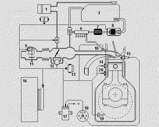
1. The adsorber
2. Fuel pump relay
3. Fuel tank
4. Vent valve
5. The regulator of pressure of fuel
6. Drive fuel
7. Fuel filter
8. Fuel pump
9. Measuring the mass of air
10. The injector
11. Air regulator
12. Idling speed controller
13. The throttle sensor
14. The coolant temperature sensor
15. Spark plug
16. The electronic control unit
17. Ignition coil
18. The ignition distributor
19. The rpm sensor crankshaft
20. Knock sensor
Publication: www.cxem.net