


")

This control system is the system multi-point injection and may includes: fuel pump, atmospheric pressure sensor, sensor air flow sensor throttle position, position sensor installation motor, sensor switch H. H., temperature sensor the air flow regulator fuel pressure, injectors, knock sensor, temperature sensor coolant sensor TDC of the first cylinder, the angular position sensor crankshaft sensor and the oxygen content in the exhaust gas (lambda probe), the electronic unit control (ECU) and the lamp indication errors. The principle of operation of the system MPI-based management of all elements from the electric component box control, which adjusts the operation of the injection depending on the sensor readings installed on the engine. Fuel through the fuel filter is fed by a fuel pump in distribution highway (drive fuel or the fuel accumulator), and through it directly to the injectors (nozzles). Pressure in the fuel path is supported by the pressure regulator (check valve), which supports the optimum pressure is directly dependent on the vacuum in the intake manifold.
The quantity of fuel injected into the inlet the manifold of the engine, depends on the opening time of the injector, which is determined by the ECU in based on received signals from the system sensors. The injector is from electromagnetic needle valve and is managed directly by the generating unit (ECU). The air necessary for the preparation of the fuel mixture is fed into the system through the air filter in the case of which temperature sensor the intake air and the air meter flow. The air flow meter outputs on the ECU information on the number air entering the system. Position sensor throttle valve associated with the gas pedal, gives information on the ECU, which takes into account its management system. In addition, the throttle body there is a regulator of H. H. (installation motor) sensor with its provisions. To maintain the cleanliness of the exhaust, the system uses feedback through the sensor the oxygen content in the exhaust gases (lambda probe), which is mounted on the exhaust the manifold. For indicating errors in the injection system, on the dashboard mounted lamp "CHECK ENGINE". If there are errors in the system have the ability to read error codes from ECU memory with initialization self-test that can be produced via the diagnostic connector.
The block diagram of the control system fuel injection Mitsubishi MPI"
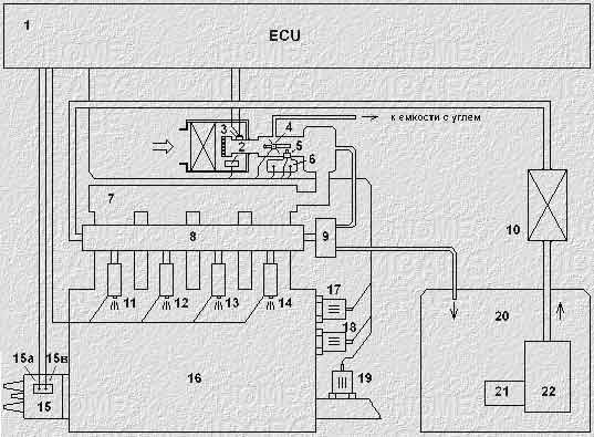
1. the electronic unit management
2. the air flow sensor
3. the air flow meter
4. the throttle sensor
5. sensor switch H. H.
6. idling speed controller
7. intake manifold
8. drive fuel
9. the regulator of pressure of fuel
10. the filter of thin clearing of fuel
11. the injector of the 1st cylinder
12. the injector of the 2nd cylinder
13. the injector of the 3rd cylinder
14. the injector of the 4th cylinder
15. the ignition distributor
15A. the TDC sensor 1 cylinder
15V. the crankshaft position sensor
16. engine
17. knock sensor
18. the thermode O. J.
19. lambda probe
20. fuel tank
21. fuel filter
22. fuel pump
Publication: www.cxem.net