


")

The owners are all ways of trying to protect their cars from the intruders. The car, standing in the yard at night at home can be easy prey, the more that is expected to be a liability law breaking the silence at night, restricting the use of alarms. More a reliable way to protect the car in the yard - installation of metal awning ("shells"). The proposed system radio informs the owner about the fact penetration into the "shell".
The alarm signal can be transmitted on one channel citizen's band communication and adopted the simplest CBS radio - Ural-P", "Laspi", etc. Only need to make a transmitter that generates this alarm on the frequency of such station.
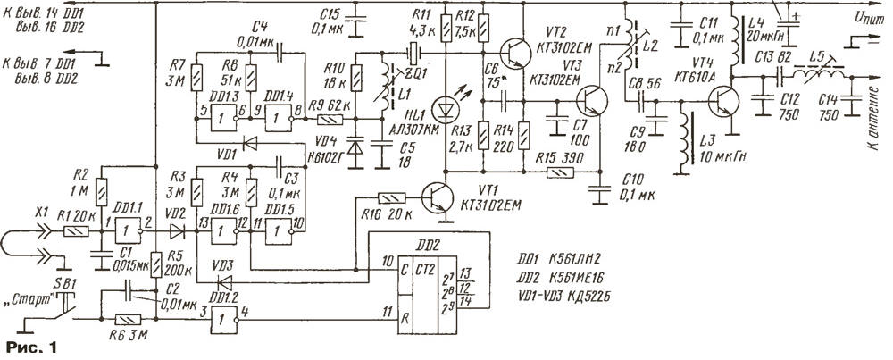
Schematic diagram of the transmitter shown in Fig. 1. The master oscillator, assembled on the transistor VT2, is excited at the frequency of the quartz resonator ZQ1, coinciding with an operating frequency of the receiving station. Since almost all radio stations of this range works with frequency modulation (carrier is modulated by frequency), in the chain ZQ1 entered the varicap VD4 and the coil L1. Changing the voltage on the varicap, you can change the frequency of the generated signal within 2…3 kHz from the center frequency.
(click to enlarge)
Transistors VT3 and VT4 function of the power amplifier. The contours and L2C8C9 L5C12C13C14 tuned to the operating frequency of the transmitter. Transistor VT1 works in key mode: transmitter is enabled if the transistor is open to saturation.
The node control transmitter made on chips DD1 and DD2. Inverters DD1.5 and DD1.6 assembled generator, excited at a frequency of about 1 Hz. At low level at the output of the element DD1.5 includes a sound generator, assembled on the inverters DD1.3 and DD1.4. The pulses of the generator, with a frequency of about 1 kHz, are used for frequency modulation oscillator.
The signal generator on the elements of DD1.5, DD1,6(1 Hz) controls the transistor VT1: switch on the transmitter, interspersed with pauses "clean" air is about the same the duration. By varying the frequency of the generators, it is possible to change the parameters of the signal alarm.
Sensor security system is the cable connected to the connector X1.
Precipice trail will lead to the fact that the low level at the input element DD1.1 replaced high and the output DD1.1 will occur is low. The high voltage level will cease to flow through the diode VD2, and the conditions will be created to run generators and the output of the transmitter in mode of transmission of alarm signal.
No matter how important the alarm, it must be limited in time. Pulses, input With counter DD2, after a while put it in a condition in which the output 29 will arise high level. Transmitter stop working, giving the air of 512 tones parcels. It will take about 9 min. Connecting the diode VD3 to other outputs of the counter DD2, you can change this time. For return the device to standby mode, press the button SB1. The same button should be pressed for the performance of the device for protection. The loop should to be shorted.
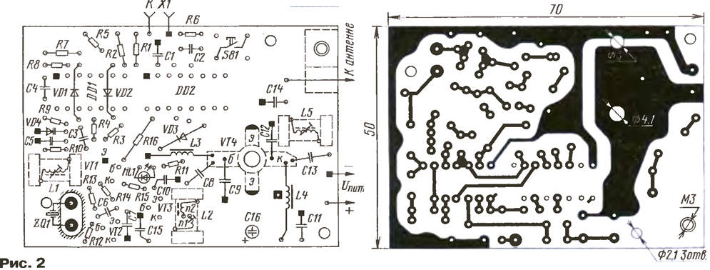
The transmitter is assembled on a printed circuit Board from bilateral foil fiberglass thickness of 1.5 mm (Fig. 2). Foil under the used parts only as a General wire and screen: in places of crossing conductors in it must to be etched protective circles with a diameter of 1.5…2 mm (Fig. 2 not shown). Connection details General wire shown blackened squares. Squares with a bright dot in the center shows the jumper between the two sides of the Board. Before installing chipset conclusions 7 DD1 and 8 DD2 folded to the side for soldering directly to the foil common wire.
(click to enlarge)
All resistors - MLT-0,125. Capacitors C1-C4, C10-C12, C14, C15 - km-6 or K10-176; C5-C9 - CD-1; C13 - CD-2; C16 - oxide with a diameter of 6 and a height of 13 mm. Inductors L3, L4 - D0.1.
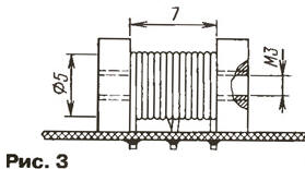
Coil L1 contains 60 turns of wire sew-2 0,07 wound coil to a coil, L2 - 13 turns (n1=7, n2=6) of PEV-2 0,48, L5 - 11 turns of wire sew-2 0,56. Coils have the trimmers carbonyl MH. The design of the contour of the coil L2 and its PCB is shown in Fig. 3. Coils L1 and L5 are different only in the absence of dissipation. The coil L1 is glued to the Board.
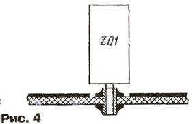
Quartz resonator can just solder. But the real resonance frequency is often significantly different from the bearing on the case. Selection the resonator is simplified if the Board is not solder the resonator, and nests under his the pins (Fig. 4). Such nests (internal diameter 1 mm) can be found in some the connectors.
The circuit Board is mounted on the front panel - plate cut from sheet of high impact polystyrene (hole 02,1 mm in the Board are for its mount). This same material can be glued together and the transmitter housing, the author's version he had the dimensions 78x58x28 mm.
To establish the transmitter is transferred to the mode of continuous radiation without the modulation. Short wire jumpers connect the common wire the collector of transistor VT1 (this ensures continuous power to the transmitter) and left (according to the scheme in Fig. 1) plate of the resonator ZQ1 (this excludes the influence of chain L1VD4C5).
To the antenna output connect the 50-Ohm dummy (two included parallel resistor MLT-0,5 100 Ohms), high frequency (≥30 MHz) voltmeter and frequency meter. To connect the connector X1 simulating the plume jumper.
Filing for transmitter power, tuning coils L2 and L5 achieve the greatest the voltage on the antenna equivalent. Given in the load capacity is calculated as The radio isotopic laboratory (W) = U2/50, where U (V) is shown by a voltmeter effective value high-frequency voltage. The transmitter can be programmed without a voltmeter, if as the antenna load to take the bulb 2.5 V 0,068 A: the best the setting will correspond to the maximum brightness of its glow. Brightness this lamp can be the judge of that, very roughly, of course, and radiation power.
If the displayed frequency meter frequency different from that required by more than 0.5 kHz, quartz crystal replace the other.
Then remove the jumper with quartz resonator and the tuning coil L1 set the frequency to 2 kHz above working (if the loop a, the output item DD1.4 is set to the high voltage level, which refer to the frequency the master oscillator up). If the connection astatoreochromis chain L1VD4C5 resulted in a failure to generate and is not restored at any position the podstroechnik L1, it is recommended to select the capacitor Sat. If quartz the resonator does not work at the third harmonic, and the main (which is rare, but case), the number of turns of the coil L1 is necessary to reduce 2-3 times and pick up the capacitor C5.
The dependence of the main characteristics of the transmitter from the voltage of the power source shown in the table.
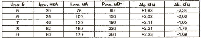
Here: Dir - the current consumed by the transmitter in standby mode (loop a); Nepr - the same as in the continuous radiation; radio isotopic laboratory - radiation power; ΔfB - the deviation of the oscillation frequency up when the voltage on the varicap VD4 close to supply; ΔfH - reject down when the voltage on the varicap close to zero. From the table shows that the change in the voltage of the power source has little effect on the frequency the radiated signal. At a voltage of from 5 to 9 In the signal remains in the channel strip connection.
The final configuration of the transmitter completes the tuning coil L1 at the hearing on best tone signal in the dynamic receiver head.
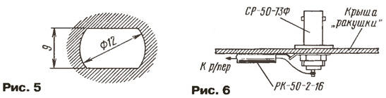
On a metal roof "shells" set the socket to connect the antenna. In Fig. 5 shows the configuration of hole antenna connector SR-50-F, and Fig. 6 - connect cable. One end of the cable is attached directly on the Board transmitter clamping bracket, the other is soldered to the connector.
To the power requirements are simple: the voltage - 6…9 V, the load current is not less APR - capacitance source must provide enough long his work. For example, DL223A lithium battery (voltage - 6 In, capacity - 1400·A h dimensions - 19,5x39x36 mm) will not care about nutrition for several years. The battery can be composed of cells, but serve this battery is much less.
If you intend to use the transmitter in cold regions, it is necessary that the power source is maintained efficiency and at low the temperatures. Here is a galvanic battery lithium also out of competition - their temperature range from -55 to +85 °C. Conditionally suitable (in winter) alkaline battery (-25…+55 °C). Totally unsuitable RC and SC (0…+55 °C). Less "frost" batteries. Thus, the temperature range Nickel-cadmium and Nickel metal-hydride batteries - -20…+45 °C, and lithium - -20…+60 °C.
The "shell" can be set to any antenna CB range. Need "range" of the channel (typically a few hundred meters) make even the antenna of the portable radio. However, this assurance can only give direct experiment: in urban areas with low located the emitter of the interference signals at the receiving end is almost unpredictable.
In conclusion - on the receiver. In this capacity, single-channel CB radio produced once our industry, only attractive one: almost they all have long lie unattended. Although the radio "odnoklasniki" may to work and without alteration, it is better to finalize it. First of all, it you must enter the squelch (device comprising USC receiver only when the appearance in the channel of the carrier frequency). The developers of the first domestic constantly Sizzling stations considered squelch unnecessary luxury. Then to increase the power of the signal at the output USC and, if necessary, the gain of RF tract. You can experiment with ARU: to increase or decrease its performance or even shut down.
Of course, the always-on to the reception of the radio station will be required and network the power source. In this capacity, suitable network adapter that has the desired the output voltage and overheating after prolonged use.
The receiving antenna "portativki" may be her own. But better to make antenna, securing, for example, on the balcony. Its metal fittings, connected to the connector housing, will serve as a "counterweight". Staffing antenna "portativki" can be strengthened and just on the outside of the window frame. In this case, as opposed to (it is connected to the connector shell) use loose-hanging conductor with a length of about 1.5 m.
Antenna from "portativki" requires moisture protection (especially its extension coil and antenna connector). Easiest way to put her on a narrow plastic or rubber case.
Author: Y. Vinogradov, Moscow