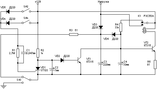
Simple and reliable alarm system. Control - just one switch. Sensors penetration - conventional switches, who, when working with the circuit performs its intended purpose, for example, the buttons on the doors. Enough for one of them to withdraw for a short time and the scheme will work. The scheme gives himself only through 10 sec. During this time, the host can turn off the alarm, and the burglar to think that this is missing.
In security mode the device consumes, depending on the parameters used details: in my case, it is possible to measure failed because of its small value.
This scheme was developed a long time ago and was going from improvised parts.

The principle of operation
Elements SA2-SAn - sensors penetration. Diodes VD5-VDn serve for decoupling sensors if they are used for other purposes. In some cases, the diodes can be eliminated.
The power supply voltage supplied from shutting sensor, via R1 C1 is supplied to VD1. Circuit R1 C1 generates a short pulse of current, even if the sensor is left in a closed condition. The capacitor C2 is not gives a trigger signal when the enable SA1.
The elements C4, R4, R5, VT2, K1 assembled multivibrator and output key. The duration that K1 is in the engaged position selected by the resistor R5, and off - R4. Total frequency pulse C4 is set. This part of the scheme requires careful settings. I got a frequency of 2 Hz.
C3, VD3, VD4 - the node that generates a delay signal when the sensor circuit. It is necessary to disable the alarm when you open the door. The length of the delay is set capacitor C3. Resistor R3 provides a capacitor discharge when power is turned off.
The site, which disables the alarm after the response was not developed because of false closures sensors on the doors, trunk and hood of the car does not happen.
Details
The scheme consists of a small number of available items. VD1 - any low-SCR, for example CU. You just need to pick C1 (increase, if not triggered when the sensor circuit), R2 (reduce, if not triggered, but if it is possible to increase) and C2 (increase, if triggered at power up). Diodes - any low. Relays K1 - RASA, but it can to commutate the load current less than 1A. If you apply more powerful relay, you will need to greatly increase capacity capacitors C3 and C4 (and, consequently, the size of the device). Therefore it is better powerful relay connected to the output RASA. Transistors - any, with appropriate structure and VT2 must be able to withstand the starting current relay. SA1 - any compact the breaker.
Types of capacitors C2, C3, C4 depend on climatic conditions, which will be operated the alarm system. For the cold winter it is better to choose them from the K53. If using capacitors C50, the device is better to install in the car. However, the experimental sample alarm on C50 was installed under the hood and operated more than two years (filmed in connection with the transition to the new system alarm) in cold climates (the car was under the open sky), and no failure was observed.
Inclusion:
1. To enable the closed-SA1 sensor (open door). In this the position of the circuit can be indefinitely.
2. Open sensor (close the door).
Off:
1. Open door (closes sensor).
2. Within 10 sec. off SA1.
Printed circuit Board for the device was not developed. Installation was made in hinged method on a sheet of rigid cardboard, impregnated a varnish. The corps used a metal box.
Author: Asanov Marat, Ufa; Publication: N. Bolshakov, rf.atnn.ru


