If the old bell housing is out of order or just tired the monotonous beep, tempting, keeping pace with the times, to establish instead, electronic - industrial manufacturing or homemade. The efficiency of such devices even allows for them to apply offline battery. However, a direct replacement of the old call new often turns out to be impossible. The author shares the experience of solving problems.
To understand the difficulties encountered when connecting the electronic call to available in the apartment wiring, consider a scheme by which there are connected even when building a house the usual electrosonic, fed from a network 220 V.
The most common variant, shown in Fig. 1,and. It is simple, but pretty dangerous as button contacts are directly connected to the network. On four-wire circuit shown in Fig. 1,b, connected calls increased security with a magnetic system arranged such that the supply network the voltage on one of the windings still does not cause the beep. To sounded, you must close button of the additional circuit, a control coil isolated from the network. Voltage between open contacts like call - no more than several tens of volts. If the "bell" wire in the apartment performed under the scheme, replacing the call to any other difficulties usually are not causes.
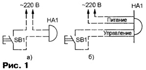
Unfortunately, four-wire scheme is quite rare. Even if she was that in building a house, for the past years and even decades many residents, in an effort to get rid of the shortcomings of the "safe" call constant consumption of energy and quite visible, especially at night, acoustic noise (hum), managed to replace the calls in their apartments normal, modifying accordingly the wiring diagram. To understand alterations can be difficult, since most of the wiring (shown in Fig. 1,a and b, dashed lines) after repeated repairs are hidden under the Wallpaper, and then immured in the wall. Available only plug directly to the call button and the ends of the wires.
Familiarity with the publications of the magazine "Radio" on the electronic housing calls, and the study of the range of these products on the market allows conditionally divide them into two groups. To first get those, the alarm which sounds at the moment supply voltage [1-4] from the low-voltage galvanic battery or battery. Calls of the second group are connected to a power source continuously, signals include a short-circuit special control circuit [5-7]. Direct connection of low-voltage power circuits and control electronic call with the network is unacceptable.
Not to search for the old or the laying of new cables, can to make the switch, provides the necessary galvanic isolation between newly installed electronic call and the network. In Fig. 2 shows a diagram one of the most simple variants thereof. The principle of operation of a simple switch. When clicking the button SB1 through emitting diode of the optocoupler U1 rectified flows diode bridge VD1 current, the value of which depends on the mains voltage and rating resistor R1. Opened the phototransistor of the optocoupler is energized, the power supply circuit or management call. An alarm sounds.
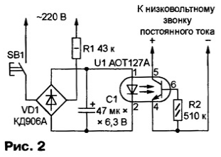
OPTRON AOTA chosen because of its high sensitivity (in most cases in the circuit emitting diode of sufficient current to 5 mA) and a significant, up to 70 mA, the output current. It is capable of switching the supply chain of virtually any electronic call at voltages up to 30 V. it is, of course, use and other optocouplers. For switching the high-impedance control circuit optocoupler can be even diode, for example, ADA.
Connecting the switch with the call, you should be shown in the diagram polarity. It is easy to determine by measuring with a voltmeter the voltage between going from call wires connected to the output circuit of the switch. If the radiant diode optocoupler requires a current of more than 6 mA, the quenching resistor R1 should be replaced capacitor, just as is done in the next device.
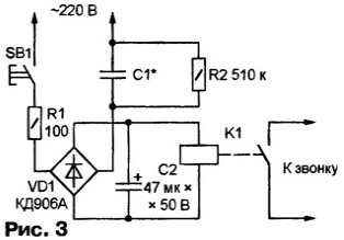
Its scheme is shown in Fig. 3. Instead of optocouplers here set small relay K1 (RES, RES15, RES, RES, RES, RES or other similar). The relay contacts can be commutated circuit calls with either polarity. Element limiting the current through the relay coil is the capacitor C1. It capacity chosen is directly proportional to actuating current applied to the relay based on the ratio of 1 UF - 60 mA [8, 9]. The capacitor must be compact, suitable for operation on an alternating voltage of 220 V, 50 Hz. For example, K73-16 or K73-17 - for a voltage not less than 400 V. the Resistor R1 limits the inrush current charging the capacitor on the switch at the time of pressing buttons SB1, through the resistor R2, the capacitor C1 is discharged in the pauses between her taps.
Unfortunately, when managing electronic call with mains operated switch lost one of the main advantages of Autonomous power call not acts, if the network is faulty. Resigned to this, you can go ahead and feed from the network the call, collecting the switch in the circuit shown in Fig. 4. Device universal, certain of its outputs will use as needed. Produced to power the ringer voltage depends on applied the Zener diode VD3. When specified in the scheme XA it In about 3, so as part falls on the diode VD2. If need different voltage, you should install the corresponding Zener diode VD3 and the capacitor C2 to the desired voltage. Current emitting diode of the optocoupler U1 if necessary, adjust the selection of the resistor R3.
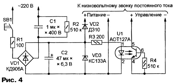
After clicking the button SB1, the voltage at the capacitor C2 increases relatively slowly. For this reason, the current through the emitting diode of the optocoupler U1 reaches the value at which the output circuit of the optocoupler is closed, after the voltage was sufficient to bring the call to a working state. For most calls this is normal" But there are also those that the result of applying voltage in open-loop control circuit reproduce only the first of the saved tunes regardless of the position their switch.
In such cases, to take advantage of all the functionality call, you have to nourish it from a galvanic battery, turning it off in the intervals between alarms. But the tension generated by the switch when pressing the button, this battery can be recharged, which will significantly increase the life service.
As a home can be successfully applied electromagnetic calls from old telephones. The sound of them quite nice, regulate the volume mechanically. Lovers of the exotic can save and the phone, placing it on the wall or on a table near the door. Although the ringing voltage on the telephone line variable frequency of 25 Hz, the call works fine and the network frequency of 50 Hz. Amplitude value supplied to the coil voltage must not exceed 120 V, supply current is 5...20 mA.
To connect a phone call follows the scheme shown in Fig. 5. Diode bridge VD2 included in the diagonal of the Zener diode VD1 bilateral form the limiter voltage of ±120 V. If the call noticeably winding heated Zener limiter need to be replaced by another for less voltage, for example, from D.
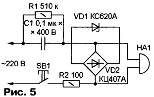
The limiter can be performed without the bridge VD2. Simply connect in parallel the winding of the ringer circuit of two identical Zener diodes connected counter-consistently. A special clamp diodes needed voltage. Sometimes you may need to increase or decrease the operating current, accordingly, by changing the capacitance of the capacitor C1.
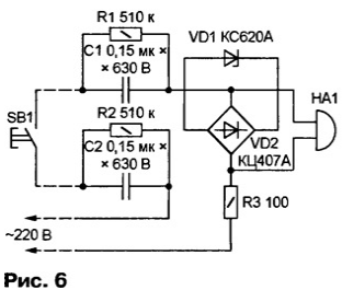
When you connect a call on any of the above schemes, at least one of the contacts of the button SB1 is directly connected to the network. But in it is shown in Fig. 6 four-wire modification of the previous scheme and firefighting capacitors (C1 and C2) are in the circuit of each contact of a button. Therefore, when random touch any of the pins on the current flowing through the human body, will not exceed the allowable values [10]. Capacitors should be rated at operating voltage 600 V. to Increase their capacity is unacceptable, so call HA1 must be sufficiently sensitive.
The switch scheme of high security, suitable for the management of any calls as low voltage and designed for power supply of 220 V, it is shown in Fig. 7. Selecting him for the relay K1, should pay attention to the holding current is its anchor in the triggered state is not exceeded for human values, and the contacts necessary to withstand the stress and call current. Has proved to be excellent relay RES-54 trip current 3...4 mA, a holding current less than 1 mA, coil resistance 4 ohms. Each group its contacts allows the load to 0.1 A. Using this relay, it is possible to reduce the capacity of the quenching capacitors, and with it the dangerous fault current contact the SA1 button on the ground, more than double compared to the switch the circuit shown in Fig. 6.
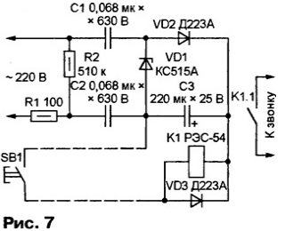
The operation of the device requires some explanation. In the initial state limited the Zener diode VD1, the voltage on the filter capacitor C3 is slightly higher voltage of the relay K1. So when you press the button SB1 relay and the capacitor C3 discharges through the winding. However, the "charging" current passing through the circuit C1-VD2-relay coil K1-closed contacts of the button SB1-C2, remains sufficient to hold the relay in the triggered state.
After releasing the button, the current through the relay coil is stopped after 1 2C... the voltage across the capacitor C3 reaches the old value and the switch is ready re-firing.
If necessary, you can reduce the capacitance of the capacitors C1 and C2 another two times, replacing the half-wave rectifier full-wave bridge. This will double the average value of the current flowing through the relay coil K1 when the button is pressed SB1.
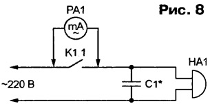
To reduce the load on the relay contacts or button, which closes the circuit of the call alternating current can be connected in parallel to the call HA1 capacitor C1, as it is shown in Fig. 8. Reactance of the capacitor at the frequency of 50 Hz must be equal and opposite in sign to the inductive component resistance of a winding of the call. The capacitor need of capacity choose the minimum indications temporarily connected milliammeter AC RA1.
Due to the small number and small size elements to accommodate any of switches you can use are always available inside the electronic call free space.
It should be noted that a correctly assembled and operable switches almost safe in operation, but by assembling and establishing't forget that some elements are directly connected to the network. You must comply with caution and take measures of protection against electric shock.
Attention! None of the proposed devices may not be recognized as completely safe. According to existing standards for this in addition to limiting the current, required that the isolation between connected and not connected to the network chains withstand voltage of several kilovolts, and the distance between the related wires, hinged or printed, exceeded the allowed value (usually not less than 5 mm).
Literature
Author: A. Latico, Dnepropetrovsk, Ukraine


