Now nobody is surprised if when pressing the bell button located at the front door of the apartment, instead of the usual "Tr...R" or "Ding-Dong" bell fragment of popular pieces of music or voice of animals and birds. In stores that sell home electronics, there are many variants of domestic and foreign musical calls, which are often even cheaper than conventional Electromechanical. Most domestic calls are based on a chipset series UMC-7 or UFT-8, included on almost the standard scheme. In Amateur literature repeatedly described the shortcomings of the model scheme (the sharp sound caused by pulse the nature of the output signal, briefly press the button "start" the first tune sounds to the end, etc.) and proposed improved options switching circuits (L. 1, L. 2).
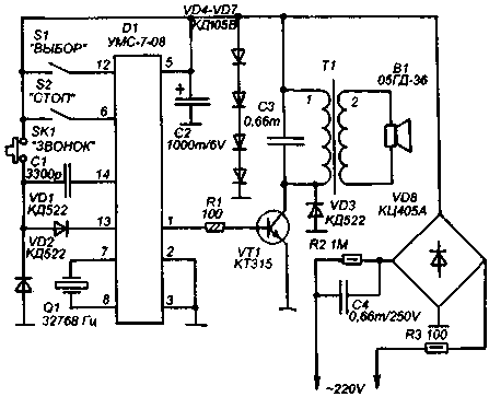
Figure 1 in the text shows a diagram of another version of such a call.

Fig.1
Unlike typical that the sound became more relaxed and soft, and briefly press the button "CALL" the device is fully loses a piece of music. The sharpness of tone, enabled by the model scheme is due to the fact that the dynamic driver included in the collector circuit of the output transistor switch, proceed unipolar rectangular current pulses. While such a signal rich in high frequency harmonics that are coming into resonance with the coil of the speaker and its mechanical system and acoustic design, give a portion of the music is not inherent color. In addition, the current flowing through the voice coil dynamics contains a fixed component, which shifts the diffuser and reduces the volume. In the intervals between the different sections a song appear loud and sharp clicks caused by differential this DC component.
In addition, the transistor operation key in a pulsed mode at low impedance the load leads to the fact that the resistance of the transistor in saturation mode is much larger than the voice coil of the dynamic head. Therefore, a significant portion of energy is spent on heating of the transistor and not speaking of the diffuser.
These drawbacks can be eliminated if the speaker connected to the output transistor of the cascade via a matching transformer having a high impedance primary winding and a low impedance secondary. In addition, including parallel the primary winding of the capacitor, we get a resonant circuit that is configured to the average frequency of music. The presence of the transformer will agree low-resistance coil speaker with a relatively high impedance output of the key, and the presence of the resonant circuit smoothes rectangular pulses, making them more close to sinusoidal and suppresses unwanted high frequency harmonics. Since the factor of the circuit is not high, played all the notes laid in the jukebox.
The presence of resonance in the circuit causes the voltage on the primary winding of the transformer is slightly above the supply voltage of the chip, and it leads to increase the sound volume.
The second defect model scheme is that at short-term briefly press the button "CALL" melody sounds. Case that playing time in this case is determined not by length musical fragment, and the capacitance of the locking release button. In the circuit shown in figure 1, with the inverted output of the chip (pin 14) impulses through C1 receives the detector VD1 and VD2, so on the 13th o chip will present unit all the time while musical sounds fragment.
Eats music a call from a transformerless power supply the rectifier D8 and parametric stabilizer composed of a chain of diodes VD4-VD7, which together falls to 2-2. 5 In and jet quenching resistance capacitor C4. The capacitor C2 smoothes pulsations obtained permanent current.
As the basis for a call is used translational subscriber the speaker "Sketch". It has a plastic case, speaker and transformer. All this is used in design, except volume control, who is excluded.
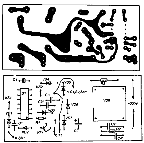
Most of the details of the call are on a small-sized circuit Board, drawing and wiring diagram of which is given in the text.

Fig.2
Board made of Micarta with double-sided folgirongi. You can use and another foil insulation material, which is used for printing boards. On the Board are the buttons S1 and S2 (SK1 displayed on the front door) and the transformer.
The chip can be UFT-8 or UMC-7, additional digits (for example UMC-8-08) say about the musical repertoire of the chip. The buttons S1 and S2 located on the bell housing, with the S1 button to select the melody for further playback, and press S2 to stop the playback.
The capacitors C3 and C4 each composed of two parallel connected capacitors 0.33 UF each, to the circuit they are marked as Sz' Sz and C4' and C4".
Rectifier bridge CCA can be replaced by a bridge made up of diodes CDW or CDW,D226.
In the absence of the substrate, you can use the transformer from the output cascade old transistor radio and any speaker of 0.1-3 watts.
The establishment of a correctly assembled device from the healthy parts consists in choosing the value of capacitor C1 in such a way that at least pressing the SK1 was full, single playback music fragment. If the capacitance C1 is too high, the machine can play melody several times in a row. Optionally, you can set more precisely the capacity of the NW, so that the timbre and volume of the sound were the best.
Literature
Publication: www.cxem.net


