Another option e-copycat - it allows to simulate the roar of a running internal combustion engine and tonal the signal beeps. This versatile device will help to "revive" different toys, maquettes and models of cars and mechanisms, such as automobiles, motorcycles, tractors, diesel locomotives.
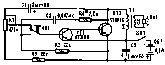
The device is based on an asymmetrical multivibrator, collected on transistors VT1 and VT2 phase patterns (Fig. 1). To expand possible simulator managed through the use of two separate customizability circuits with different time constant, switched push-button switch SB1. The device is a toggle switch SA1, giving the battery voltage GB1.
In position SB1 shown in the diagram, the oscillation frequency the multivibrator is determined by the parameters of timing chain R1R3C1, connected to the base of the transistor VT1. The generator operates in the metronome mode, producing periodically recurring pulses with significant pauses between them - running "motor". It sounds reproduces dynamic head BA1, enabled via the transformer T1, the clerk collector the burden of the transistor VT2. Frequency "exhausts" adjust variable resistor R1. In the top circuit position of the engine "exhaust" rare. Turning the engine in the down position, the resistance of the resistor is reduced - "motor" turns up the speed, the speed increases.

Fig. 1
If you need to file an audible tone, press the button SB1, and with the base of the transistor VT1 will be joined by another chain R2C2R4, which converts the device into an acoustic frequency generator. The duration of the beep depends on the time you press the button.
In the real mechanism, say, in the car, loud signal horn drowns out the noise of the engine, this circumstance included in the simulator - you should release the button, the switch signals and heard the noise "engine". When the "engine" should "drown", his "momentum" is reduced to a minimum, and then cut the feed - motor stops working, but not immediately. Heard another three key blank stroke with decreasing volume, due to the energy stored capacitor C3.
About the details. The silicon transistors low-power: VT1 (n-p-n) any series CT, CT, CT, CT, KT315, CT, CT; VT2 (p-n-p) - any series CT, CT, CT, CT, KT361. Permanent resistors MLT-0,125-MLT-0,5; variable resistor of any type, preferably group A. Oxide capacitors K50-3, K50-6; C2 paper, metalloboranes or ceramic (BM, MBM, KLS).
Transformer - the output from any transistor radio. Used only one half of the primary winding, having an average conclusion. Dynamic head - capacity 0,1-2 W and with resistance voice coil DC 6 - 10 Ohms. SA1 toggle - switch of any type, for example PT-1-1, MT-1; SB1 - button latch-type KM1-1, CMD-1 or improvised on the basis of the microswitch MP, and P2K without the retainer. GB1-battery 3336L ("ruby") or three consistently United element 343, 373.
Assembled without error, the device with the use of serviceable elements begins to function immediately. But since the maximum and the minimum engine speed varies in different cars, the capacity capacitor C1 should be selected within 1-5 UF. Tonality signal determines mainly the capacitance of the capacitor C2, which ranges from 0,033 to 0.25 µf, and the volume (and within the small key) set selection value of the resistor R4, thereby modifying the duty cycle of audio frequency. To get more deaf "exhaust", the winding I of the shunt capacitor 0,047 UF.
Sometimes the inverter speed "motor" (resistor R1) combined with the power switch. In this case we recommend apply variable resistor with switch - TK, TKD or CP3-106.
Author: E. Sawicki, Korosten, Zhitomir region; Publication: www.cxem.net


