


")

"Flasher" - turn indicator (Fig. 1)
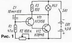
The basis of the design is asymmetrical multivibrator in two transistors of different structure. Load multivibrator - filament lamp HL1 for a voltage of 3.5 V. the Frequency of its outbreaks depends on the capacitance of the capacitor C1 and the resistors R1, R2. The variable resistor R2 change smoothly the frequency of flashes of the lamp. When moving its slider to the left it under the scheme increases, and to the right decreases.
Instead of lamps you can install the led ALA, but it consistently to include a current limiting resistor 100 Ohm and install the capacitor C1 larger capacity - 50 UF.
One use of "flashing lights" - turn indicator for a Bicycle. Lamp install the back - one to the right of the Bicycle wheel and the other on the left. Instead switch SA1 need to install the switch with the middle position and two groups of contacts. One group of contacts to turn the power on, and the second connected to the collector circuit of the transistor VT2 lamp right or left turn indicator.
The humidity indicator (Fig. 2)
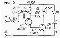
This is the electronic "nanny". If the above multivibrator a bit to convert, get the humidity indicator. In the nests of X1 and x2 is inserted gauge - two insulated from each other conductor, for example, associated together segments of a single bonding wire in the insulation length 8… 10 cm. If such a sensor is dipped in a glass of water, the resistance between conductors will decrease and the dynamic head will beep. It should be removed the conductors and the sound disappears.
The humidity indicator can be used in everyday life, say, as electronic "nannies". You need to make some other sensor, comprising two thin tinned wire length 1.5…3 cm, sewn to the segment tissue at some distance from each other. It is placed in the diaper of the baby. As soon as the sensor gets wet, the resistance between its electrodes dramatically reduced. Turns on the multivibrator, and will sound an alarm for parents.
Siren (Fig. 3)
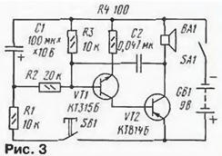
Another option is the use of asymmetrical multivibrator - demo siren. Immediately after the power switch SA1 in sound dynamic head will not, because on the base of the transistor VT1 is no voltage offset. The multivibrator is in standby mode.
You press the button SB1, through the resistor R1 starts charging the capacitor C1. The bias voltage on the base of the transistor VT1 is increased, and when a certain value, the transistor will open. In the dynamic head of BA1 you hear the sound of a certain tone. But the bias voltage continues to grow, and the tone of the sound changes smoothly up until the capacitor completely charges. When specified on the diagram the values of capacitor C1 and resistor R1 this process continues for a few seconds.
Once you release the switch, the capacitor will begin to discharge through resistors R2, R3 and the emitter junction of transistor VT1. The tone of the sound will change smoothly, and when a certain bias voltage on the base of a transistor the sound disappears. The multivibrator will return to standby. The duration of the discharge capacitor depends on its capacitance and the resistance of the resistors R2, R3.
In standby mode siren consumes little current, so the switch contacts can be closed for a long time. This is necessary, say, when using the device as a home call. When completing the contact of a button, current consumption increases to several tens of milliamps.
"Get it thread" (Fig. 4)
The so-called attraction, which also contributes unbalanced the multivibrator. On a small wooden stand strengthen a thick sewing needle, labeled X1 slot. The fact that in Fig. 4 is designated as a fork X2 - thin (0.2 mm) copper wire with an enamel insulation. Task - threading "string" (end of wire) in the eye of a needle so that did not touch the end face with needle. This is overseen by the detector touches made on four the transistors.
The first two (VT1, VT2) - electronic key, connected a test light filament HL1 to the power supply socket and the plug(in other words, when you touch "thread" the eye of a needle). On the other two transistors assembled multivibrator - he connected in parallel to the lamp. As soon as the lamp will flash, it will show voltage. Immediately earns the multivibrator, and the dynamic head of BA1 you hear the sound. The tone depends on the capacitance of the capacitor C2 and the resistance of the resistor R3.
Touch "thread" with a needle can be instant. Will it the detector will flash if the lamp? In the simplest case, it is unlikely to have time to heat up. But in the device are of such a scenario is provided for the which entered the detector capacitor C1 and resistor R1. On this chain and is fed through the needle and "thread" voltage. Even their instant touch it is sufficient that the capacitor has time to charge up to the voltage of the supply battery GB1. And then begins to discharge through resistor R1 and a composite transistor performed at VT1, VT2. And though "thread" doesn't relate to the eye, the lamp is lit, and dynamic head the sound. It lasts long - less than a second.
Dynamic head - 0.5 GDS-2-8, with with small dimensions sufficient the volume of the sound.
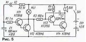
The electronic bell (Fig. 5)
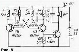
Adding to the previous multivibrator amplifier cascade transistor VT3. get electronic bell. Due to the dynamic head of BA1, the volume is sufficient that the sound was heard in the apartment. Button SB1 - bell installed at the front door. Dynamic head - 0.5 GDS-2-8.
Simulator sounds of raindrops (Fig. 6)
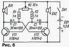
Cap… drip… drip… - the sounds from the street in the rain or in the spring when from the roof falling drops of melting snow. These monotonous sounds, like the murmur of the brook, many people are calming. To verify that it says will help the simulator, made under the scheme of the symmetric multivibrator with two transistors.
Loads the shoulders of the multivibrator are dynamic head of BA1 and BA2 (as in the previous design, type 0.5 GDS-2-8). The variable resistor R2 can to adjust the frequency of dripping in a wide range.
Probe for "continuity test" installation (Fig. 7)
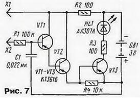
Before proceeding to review the assembled structure, need "ring" installation, i.e. to verify the correctness of all connections in according to the circuit diagram. Usually for these purposes hams use an ohmmeter or avometr. working in a mode of measurement of resistance.
Often, this device completely replace a compact probe, which signal safe one way or another chain. As an example of the proposed to assemble the probe at three transistors and the led. Transistors made relatively sensitive amplifier having a high input impedance (several megohms) that allows you to "test" visokom-ing chain.
While the probes X1 and x2 are open, the transistors are closed, HL1 led is extinguished. When the circuit of the probe, or when the poll is" defective connective chain Assembly, the transistors are opened and the led flashes.
Most led's brightness is observed at low resistance check chain. With the growth of this resistance, the brightness of the led decreases. That was not false signal, and, when the interference of the alternating current on the input circuit the probe, set the blocking capacitor C1.
If instead of a X1 probe set alligator clip and probe X2 to connect with the bracelet, worn on the arm, "poll" can be carried out differently. A clamp connected to one the ends of the connecting circuit, and a finger touched another. With proper circuit the led will be lit.
In the probe there is no power switch because current consumption mode wait, when all transistors are closed, shall be void.
The radio receiver of direct amplification (Fig. 8)
It is designed for reception of radio stations in the medium wave band (CB). It the sensitivity is sufficient to receive signals from local and remote workstations. Listen to them on the miniature head phone BF1 (TM-2).
Oscillating circuit magnetic antenna WA1 consists of inductors L1 and the variable capacitor C1 (CP-180). A dedicated radio frequency circuit the signal is sent through the coil and the capacitor C2 to the radio frequency amplifier, performed on the transistor VT1. With the load of the amplifier (resistor R1), the signal served on the detector, assembled on the diodes VD1. VD2. RF component the signal is filtered by capacitor C5. a component of audio frequency signals 3H) is allocated to the variable resistor R. 5. This is the volume control.
With engine variable resistor signal supplied by the two-stage AF amplifier on transistor VT2. VT3. The load of the amplifier - headset BF1.
Magnetic antenna is made on a round rod of ferrite with permeability of 400 or N. Will accept standard rod used in small industrial transistor receivers. If desired, it can be shortened to 100.. uh, 80 mm high. need to collect by this scheme "pocket" radio. Coil L1 needs contain 65…70 turns of PEV-1 with a diameter of 0.1 mm, a L2 - 3 turns of such the same wire. Coil wound round and have a distance of 3 to 5… mm from each other.
If you wish to work on a range of long waves (LW) the number of turns of the coils increase threefold. Bandwidth, shutting off during the restructuring of the capacitor variable capacitor C1. set selection of the number of turns of the contour of the coil.
Author: S. Shipovskih