


")

Currently Amateur radio continues unabated. Ham come to the rescue of new technologies, computer modeling, more free the search for information. The details began to get much easier than it was before. Over the Internet can buy, both Russian and imported components.
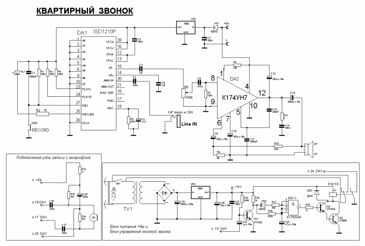
Your attention is invited schematic of the "Apartment" call. Many people collect calls-tweeters, calls with a set of tunes (for example, Musical call to the IMS UMS etc.
This call is made the two chips that are not, currently, deficit. Chip CON - WOOFER and amplifier chip ISD1210P. Chip ISD1210P this chip recording and playback of sound within 10 seconds. For apartment call, I believe this is the optimum time. In this diagram, sound can be recorded directly from the line output of a tape recorder by connecting it through a resistor to the capacitor C3. Options recorded fragments can be variety: voice, music or a combination.
(click to enlarge)
Fig. 1 Schematic diagram of the call
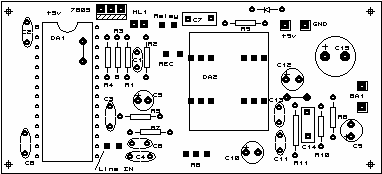
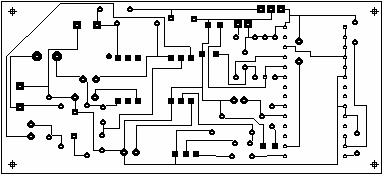
Fig. 2 a printed circuit Board,
I used the following. In the music editor wrote the sound of the Gong (the instrument is the vibraphone). Converted it into a WAV file and added voice message: "Lord, You got".
Then recorded the resulting file on a tape recorder, and with him in the chip in the other half. All information took 5 seconds at a time. File in WAV format takes a little more than 80 kilobytes. zvonok.wav
For triggering a relay after pressing the button, we need to write on 0.5 second sinusoidal signal, at the beginning of the file, with a frequency of 15-18 Hz. When you click the call with SA1 chip Corder through the capacitor C4 is supplied the capacitor C22 signal. Passing through a chain D5 R17 and logical the element DD1.1. creates output 1 high level. After passing through the resistor R19 and the amplifier transistors Q1 and Q2, makes work relay contact closure. By locking the call button and the leg 24 of the chip ISD1210P, the device remains plugged in and plays a recorded fragment. After the sound fragment relay for 3-5 seconds holds the contacts closed. Then the output 1 DD1.1 appears low level, and the relay is again triggered on the break contacts, de-energizing thus the entire device.
Resistor R18 is governed by the delay time of the outage. In power transistor VT1, the diode D6, resistors R17, R18, which manages the relay is made on the principle of "Relay delay". It is used to turn off the tape recorder at the end of phonograms. If You want to record a fragment from a microphone, use a node record from the microphone. At the end it can be disabled. Chip chip-Corder can be rewritten 100,000 times.
Amplifier CAN included in the model scheme, with the introduction of corrective chains to reduce the %I. D. Features in the setting has not.
The printed circuit Board to the power supply unit was not designed.
Literature
1. Gromov, A. Radomski "improvement of the PARAMETERS of the AMPLIFIER ON KUN"
2. N. And.Drobnytsya "ELECTRONIC DEVICE FOR radio Amateurs" Moscow "Radio and communication" 1985.
3. ChipCorder*
Technology by iso ISD1200 Series Single-Chip Voice Record/Playback Devices 10 and 12-Second Durations."
Author: Anatoly Nikolaevich Patrin., G. Kirsanov, Tambov region, This email address is being protected from spambots. You must have JavaScript enabled to view it. ; Publication: www.cxem.net