


")

It is known that the residential calls, working on the principle of "telegraphic alphabet", bring a lot of inconvenience to the residents of communal apartments and come to their acquaintances. From this deficiency is easily corrected by setting the musical call. Worth only take the device described by G. Shulgin (see "Radio" № 8, 1987 G.), add a few nodes and is ready melodic ringing rooms.
Schematic diagram of musical bell is shown in Fig. 1. It designed for four rooms of a communal apartment and is controlled by four buttons (SB1 - SB4). Clicking on each of them sounds its melody.
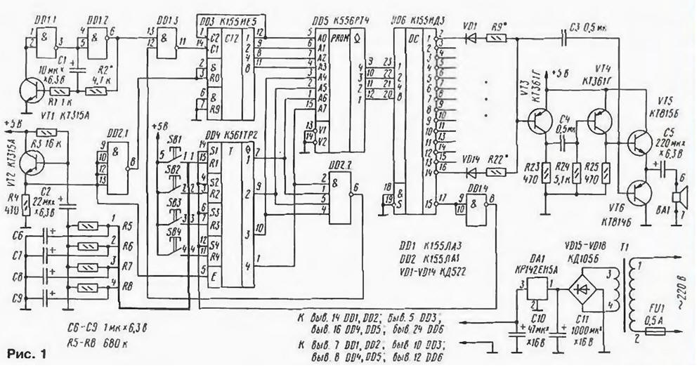
(click to enlarge)
This device works as follows. When the supply voltage node on the elements DD2.1. vr2. R3. R4. C2 resets the counter to zero DD3. The signal from the emitter of VT2 to the input E chip DD4. briefly brings it outputs in high-impedance state, resulting in the free inputs of the element DD2.2 level appears log. 1. Log. 0 output from this element is fed to one of inputs of the element DD1.3 and prevents the passage of pulses from generator to the elements DD1.1, DD1.2 and the transistor VT1 to the DD3 counter. When you click on one of buttons SB1-SB4 switches one of the triggers of the chip and DD4 the corresponding input of the element DD2.2 level appears log. 0. As a result the output of this element will be set a level lot. 1. which will permit the passage of pulse generator to the counter DD3. The counter starts to count Jr. level EPROM on the chip DD5. in the senior ranks which depending on pressed button code installed on one unit 0111, 1011, 1101 or 1110. These codes and used in the call.
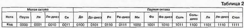
Each melody consists of fourteen notes. The playback speed, as desired, choose the resistor R2. The last code table (1111) sets the output 17 decoder DD6 the level of the log. 0. The DDI element.4 inverts this level in the level of the log. 1. which is supplied simultaneously to all inputs of S triggers DD4. returning them to their original state. The level of the log. 0. appearing on the output of the element DD2.2. again prevents the passage of pulses of the generator to the DD3 counter. Capacitors C6 - C9 eliminate interference from the network of wires on inputs R triggers DD4 and thus prevent false positives.
Version of the firmware EPROM is shown in table. 1 (address findings - 4, 7, 6, 5, block - 15, 1, 2, 3. code- 9, 10, 11, 12), and the map matching music codes - table. 2. About programming the chip CRT is explained in detail in [1].
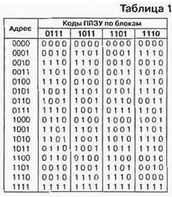
As can be seen from table 1, opportunities EPROM CRT in this device are implemented not completely - stitched only cells in blocks 0111. 1011, 1101. 1110. But if to consider the possibility of depression for two or three buttons in various the combination or use structurally altered buttons, it is possible to flash all other blocks. I recommend all older unused cell blocks to flash code 1111. because if this is not done, if you accidentally click on two button the call will loop forever, endlessly turning over an empty block, not finding the code stop
In the device, you can use resistors MLT-0.125 and any appropriate the size of the capacitors. Chip CLA interchangeable on CLA or CLA. In as VD1-VD14 will fit any small diodes KD521. KD522, CD. D2. D9. Matrix R9 - R22 composed of soldered vertically into the cost of the call resistors MLT-0.125, but other variants of its implementation [2 - 4].
The call is assembled on a printed circuit Board from double-sided fiberglass dimensions 100x60 (Fig. 2). The Board is supplied all parts except the mains transformer, which you can make your own or get ready with voltage the secondary winding 8… 10 V. Parametric stabilizer has CREA built-in protection against thermal breakdown, but will not be superfluous to attach a small heat sink.
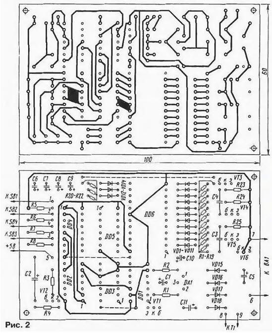
(click to enlarge)
The connection on the card with the buttons it is best to perform five core shielded wire. The shield should be soldered to the pad provided for this purpose with side installation details. The design of the call buttons is not critical and depends on capabilities of Amateur radio.
After programming the EPROM should be soldered into the Board, but if at the place of its install solder the socket, it will be possible to change the "bored" melodies. For simplify call chips instead of KIZ you can use KID, but this device capability will be reduced to the set of nine notes.
About configuring a tone generator and verify the operation of the counter and decoder explained in detail in [2].
Literature
Author: D. Kostecki, G. Kamen-na-Obi, Altai Krai