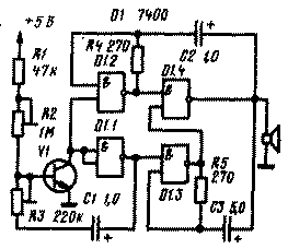
In Fig. 1 is a schematic diagram of the electronic siren, collected on a single transistor and chip. Essentially, the siren consists of three generators with different temporal characteristics. Transistor V1, the element D1.1, capacitor C1 and resistors R1 - RЗ form generator with a clock frequency of about 1 Hz. The desired repetition frequency of the signals can be picked up trimmer resistors R2 and R3.

Fig.1
Element D1.3, resistor R4, capacitor C2 and the element D1.4 make up the second oscillator with oscillation frequency is about 1000 Hz. Finally, the element D1.3 together with the resistor R5, the capacitor element C3 and D1.4 form a third generator, but a lower frequency of about 200 Hz. Termination siren loudspeaker is B1, is connected to the output of element D 1.4.
In the schema you can use the chip LA and any low-power silicon n-p-n transistor, for example KT315B.
Literature
-
Elektrotehnicar (SFRY). 1976, № 7-8
Publication: N. Bolshakov, rf.atnn.ru


