


")

Doorbells, announce the arrival of guests of any song or other sounds, in the magazine has been described more than once. In recent years they have started to collect on microcontroller, together with a simplified design significantly has expanded their capabilities. However, it is no secret that the repetition of the devices on microcontrollers are still not accessible to everyone, as it requires availability of the computer, programmer and software. Offer call made on the basis of specialized chip ChipCorder family of companies Winbond Electronics. Its main feature - the ability to use as a calling signal of any sound (speech, music, etc.) just write to a memory chip, as on an ordinary tape recorder.
A schematic diagram of a doorbell is shown in Fig. 1. It is based on microchip series ISD25x [1], which is a recorder-playback sound information. The principle of operation of a chip similar to those used in devices series ISD1200, ISD1400 [2] and is based on storage technology analog signal in a multilevel nonvolatile memory cells. Shelf life information 100 years, the number of cycles of record / playback of at least 100,000.
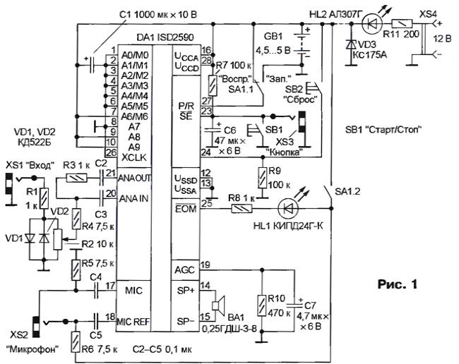
The device operates as follows. In the initial state, DA1 chip is in standby mode and consumes a small current of a few microamperes. The call button contact closure connected to the socket XS3. When a short push on it a chip reproduces the first audio fragment, and at the end returns to the standby mode. Re the call button initiates playback of the second fragment, etc E. with each successive clicking sounds of the next signal and so until then, bye not to be reproduced all the recorded information, and then the cycle will repeat. The number of fragments can be anything, but their total length is determined by the type of chip (see table).
Button SB1 ("Start/Stop") duplicates the bell and used during recording, and to check the content of the memory chips in play mode. Capacitor C6 reduces the sensitivity to noise. When you click SB2 (Reset) IC returns to the beginning of the first fragment.
For recording signals you can use electret microphone (it is connected to socket XS2) or any other source - TV, radio, the computer sound card, etc. (they are connected to the socket XS1). Diodes VD1, VD2 protect the input circuit from an unacceptable level of signal, with a variable resistor R2 sets the desired recording level.
To record a part, the switch SA1 transferred to the right (under the scheme) position (HL1 led is lit) and a button SB2 "Reset" install the chip in the beginning of the recording unit signals. Then short press the SB1, the led goes out and starts the entry of the first fragment. Complete the entry by pressing the same button (SB1), the result that the led is again lit.
Similarly record the other slices. The signal of the memory circuit constant light HL1. For recording via socket XS2 convenient to use multimedia microphone headset with electret microphone, for example, MHS101, MHS111 or similar. If you use a separate microphone, its output "+" connected to the Central contact of the socket.
When you are finished recording, the switch SA1 transferred to the original (shown in the diagram) the position, briefly press the button SB1, listen to the first fragment, clicking it again - the second, etc.
Because in the standby mode the current consumption is small, a special switch power the device does not include. If a call must be disabled for example, at night, the switch is introduced into the circuit of the power source. In the absence of need to record from the microphone circuit can be simplified by eliminating the elements C2, C4, C5, R3-R6, XS2, and in return R4 to set the jumper. For the record only microphone from the scheme exclude elements R1, R2, R4, VD1, VD2, XS1.
In your device, you can use any chip series ISD25x, but it is necessary note that the larger the capacity, the less bandwidth (see table). Best sound quality provides ISD2560, if you must have longer duration of the recording-playback, you should use ISD2575, ISD2590 (use ISD25120 is not recommended because of too narrow stripes transmission). Led HL1 - any small, preferably with high brightness, diodes VD1, VD2 - CD, KD521, KD522 with any letter index polar capacitors - any small, nonpolar - K10-17A, variable resistor R2 - GPA-4, SP4-1, etc., constant - MLT, S2-33, P1-4. Buttons SB1, SB2 - any small non-latching in depressed position, the switch SA1 - pole of any type, socket XS1, XS2 - standard connection head stereoleto. Dynamic head of BA1 any capacity 0,1… 1 W, to increase the volume should be applied with high head return. To connect with call button it is advisable to use shielded wire (cable shield is connected to common wire).
To nourish a call from a regulated unit with an output voltage of 5 V At the current up to 100 mA, and from the battery, composed of three galvanic elements or four Nickel-cadmium batteries. In the latter case, for recharging the battery using a power supply with voltage of 12V (it is connected to the socket XS4), and injected into the device elements VD3, HL2 and R11. The value of the last can be chosen according to the required charging current. The Zener diode VD3 limits the voltage on the chip during the charging process. Led HL2 - charging indicator.
Most of the parts are mounted on a printed circuit Board manufactured in accordance with Fig. 2. With battery power it is placed in a housing of appropriate size, on the walls of which fixed variable resistor R2 buttons SB1, SB2, the switch SA1, sockets XS1-XS3 and led HL1 (and when powered by the battery and the socket XS4 and led HL2). Diodes VD1, VD2 and the resistor R1 is mounted on the findings of the resistor R2, the resistor R11 on the findings of the socket XS4.
Literature
Author: I. Nechaev, Kursk