


")

Long known scheme hours performed on chips series C, still then attracts the attention of radio Amateurs simplicity of implementation varied modifications: from consoles "tick-tock" and ending nodes correction the sixth Moscow time signal. The prefix to the clock described in this article simulates the seconds hand with the help of LEDs.
The proposed device is designed to Refine the electronic clock on chips series C. It is able to turn on the LEDs in advance for any recorded program. The supply voltage is finalizing hours may be in 8…12 V
Diagram of the device shown in Fig. 1. A memory element, in which the program is the ROM chip DS1. The amount of memory used chips enough to put on it four programs control the LEDs, which are switched depending on the combinations of control signals on the address inputs A9 and A10DS1.
(click to enlarge)
Resistors R1 and R2 assembled a matching stage, which lowers the voltage logic level coming from hours, to the level of CMOS circuits by voltage power supply of 5 V. If the clock is fed from pyativoltovoy source, resistors R1, R2 and stabilizer DA1 exclude by filing a frequency of 1024 Hz directly at the input of SR counter DD1.
Dynamic display is implemented on the decoder DD3 and key transistors VT3-VT10. Counter DD1 goes through turns 8 bytes (8 bits), i.e. it is possible connect up to 64 LEDs (the extra 4 bits are simply not involved). Switching occurs with great frequency, and the eye does not notice.
Counters DD1 and DD2 are connected in such a way that the result of the division through every second of the pins 5, 6, 11-14 DD2 iterates through binary code from 0 63. But as the minute is 60, entered the site of the correction transistor VT1, which generates a short reset pulse at the end of the minute pulse. Thus, the device is synchronized every minute that is also helpful in if you press the correction button the watch when the seconds counter chip CIE reset.
Transistor VT2 assembled the node that switches the program depending on light. If the oscillator clock is assembled on a chip KIA, this no function.
All the details of the devices except for switch SA1, LEDs and a stabilizer, are mounted on the Board from bilateral fiberglass (Fig. 2).
Can use a one-sided glass fiber, replacing traces jumpers. Unused pins of chips are biting. Chip DS1 installed on the panels.
The LEDs are mounted on eight arcuate boards, seven of which contain eight LEDs and eight to only four LEDs (60 LEDs). All the Board LEDs are connected by wire MGTF small diameter and connected to the main Board by two TV inputs octal OnP-VG-8, GST-SH-25 (not shown). It is not necessary to have the LEDs in the form of a circle, they can be installed along the perimeter of the hours of any form.
Capacitors C2, C3 and DA1 chip are located on a separate Board, and DA1 mounted on a small heat sink area of 30…40 cm2.
As ROM DS1, you can use any similar IC: CRF, 2716, 27c16. Data to the flash ROM in the table.
(click to enlarge)
In hours, you can use any of the photoresistor. Instead of transistors CTA suitable KT815 with alphabetic index-G. Rigged the resistor R7 - GPA-38.
The device is assembled in the housing of the electro-mechanical clock Yantar sizes 24x24x4 cm
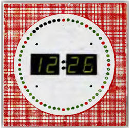
The colors of the LEDs can be any, for example, all the red (green, yellow) or alternate. Nice turns, if every fifth led highlight in a different color. When choosing LEDs should be remembered that the voltage drop across the red led is smaller, i.e. it will glow brighter than the green or yellow. Better to use imported LEDs (especially as green or yellow), as they are well lit at low current. From domestic LEDs you can use any red - ALB, etc.
Thus, in the embodiment shown in the photo, as the red LEDs used ALCM, and as green - import L93SCG (although it is better to use non-directional, so as usual the clock hanging above the direct view of the beholder). Despite the direct connection of LEDs to the ROM, the device has sufficient brightness of the room light.
Establishing device is in the selection of the resistor R2 is the amplitude of the pulses it should be within 4…5 V. the Resistor R7 are selected so that switch the brightness was synchronous with the clock.
The device draws a current of 200 mA for all of the included LEDs and 50 mA at one enabled led.
The current transfer ratio of the transistor VT2 when the temperature changes will change, so will change the ratio of the divider R6-input VT2. To to minimize this impact, as R7, you can use the trimmer, connected in the circuit of the potentiometer, and resistor R6 to exclude, by connecting the base transistor VT2 directly to the photoresistor hours. The transistor VT2 it is desirable to apply a series KT3102.
Table ROM firmware
Author: A. Plaszow, Ivanovo