


")

The offered timer is the author's attempt to find a compromise between the complexity of the device and its functionality. The task was solved by forcing relatively cheap PIC12C508A microcontroller with just one input and the three output signals to control mnogovodnymi the LCD and determine the status a large number of controls.
The device is very economical and can operate autonomously, feeding the audio signal the end of a predetermined amount of time. Provided and external Executive management device from which the timer can receive and meals. In the latter case it the possibilities are greatly expanded. Minimum duration of exposure - 1C, a maximum of 100 hours.
Schematic diagram of the timer shown in Fig. 1. On the element DD1.1 collected a crystal oscillator. With the exit of the element DD1.2 that reduces the effect of the input circuit microcontroller DD3 on the generator (it is especially noticeable when the supply voltage is less than 3.5 V), the signal frequency of 32768 Hz is input to the built-in the microcontroller DD3 timer/counter.
(click to enlarge)
Codes to the program you want from the programmer to store in memory the microcontroller shown in the table. After turning on the power, acting upon that the program, he will adjust his line port I/o GP2 and GP3 to work in as inputs, a GPO, GP1, GP4 and GP5 outputs and built-translate timer/counter mode pulse counting input GP2. The countdown is an interrupt that is generated when the counter overflows. Therefore, the accuracy of shutter speed does not depend on the stability built into the microcontroller clock oscillator frequency of 4 MHz.
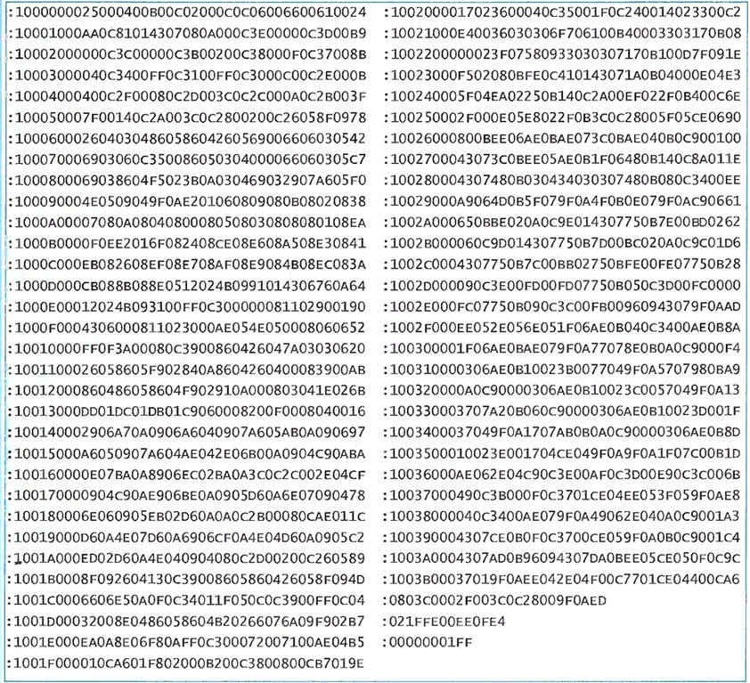
(click to enlarge)
The output GP0 microcontroller produces a signal intended for a common electrode (COM) LCD HG1. The shift register length is 32 bits on chips DD4-DD7 is for generating signals applied to the segments of all digits of the indicator, and also signals the poll buttons SB1 - SB 12 and switch configuration S1. Need to do this, the codes are received in serial form at the input D of the chip with DD4 the GP1 output of the microcontroller. The output GP4 they are accompanied by pulses of the shift. It should be noted that similar use of a shift register with a combination of control indicator and the survey management bodies became possible due to the significant inertia of the LCD. Short-term "extra" pulses on his conclusions do not cause distortion displayed by the characters.
To poll the controls on the outputs of the shift register DD4-DD7 is formed the sequence of "running zero". As a result in cycles corresponding to pressed buttons or closed contacts of switch S1, the logic level at the GP3 input of the microcontroller low, others high. At low the logic level at pin 10 of the chip, the microcontroller analyzes DD6 the signal generated by the detector low voltage power DA1 and coming on the GP3 input through the elements DD1.3, DD1. 4 and diode VD3.
Signal the end of the exposure generated by the microcontroller output GP5, arrives at the device output (pin 2 of the socket XS1) through a protective resistor R4. The same signal controls the oscillator on the chip DD2 configured to 4200 Hz the resonance frequency of the piezo oscillator HA1. As a result, the timer beeps signal. The sound can be disabled by shorting the contacts S1.7.
In standalone mode, the device feeds the galvanic battery GB1. The relay coil K1 de-energized and its normally open contacts K1.2 switch S1 (except the above-mentioned groups of contacts) is disconnected from the input of the microcontroller. It made to decrease by approximately 0.5 mA quiescent device current, which in this case does not exceed! mA (plus 2 mA when operating sound generator). Price savings - the timer works independently in a single mode: the countdown is in seconds, signals the end of the exposure - continuous duration 1 min. before the expiry of which it may be terminated by pressing the any button. Pressing the buttons in this mode are accompanied by a short sound signals.
If you submit to pins 1 and 3 sockets XS1 voltage of 5 V from an external source, relay K1 will work by disconnecting the battery and connecting to the microcontroller switch S1. Diodes VD1, VD2 reduce the voltage across the relay coil K1 to acceptable values. They prevent the timer switch on when external power reverse polarity last
Now, if contacts S1.1, it is possible to keep track of time in minutes, and with the help S1.2 change its direction from backward to forward (the display in the process of counting will increase). The following four groups manage contacts format signal the end of the exposure. S1.3 makes the signal continuous or intermittent, S1.4 removes or installs the limitation of signal duration, S1.5 inverts it (beep, if enabled, will sound during shutter speed and stop at the end). And when the closed contacts S1.6 the forced off signal the end of the exposure will occur only with the launch of the new cycle of the countdown by pressing the "Start"button.
The pin assignment of S1.7, referred to above, remains unchanged. With using S1.8 disable the "sound" of keystrokes and corresponding short pulses at pin 2 of the socket XS1.
Since the microcontroller analyzes the state of switch S1 only once (immediately after power-up) to use made during operation change device, you need to turn off and again turn on the power.
With external supply the sound signal generator is locked opened the transistor VT1. If the lock is not necessary, the transistor and the resistors R1 and R3 is not set.
Immediately after turning on the device at all positions in the indicator derived zeros, and decimal points are flashing, indicating that the timer is waiting for input shutter speed. After the introduction of each digit point in the corresponding discharge stops flashing. Attempts to enter the third digit figures 6-9 will remain unsuccessful. Here to be a number not to exceed 5. The maximum value that can be set (9959), corresponds to 99 min 59 s or 99 h 59 min depending on the unit of account (second or minute). If you make a mistake, you should click the button SB 11 ("Const.") and enter the desired value again.
The timer starts counting the shutter speed with the touch of a button SB12 ("Start"). That the count goes, according to the changing times per second or minute value the indicator and continuously "running" in his discharge point. To stop timer, enough to press the "Start" button. When running the device responds only to her. Button "Const." is valid only when the account is stopped.
If prior to the completion accounts, the voltage dropped to 2.8 V, all bits the indicator will include the decimal point. When the score goes, the fall voltage below will warn connected to the indicator inscription

- a stylized "low battery" ("battery is low"). The timer operates at a lower the voltage is not guaranteed and depends on the properties of installed instances chips. The volume of the audio signal decreases sharply already at a voltage of 3.5 V.
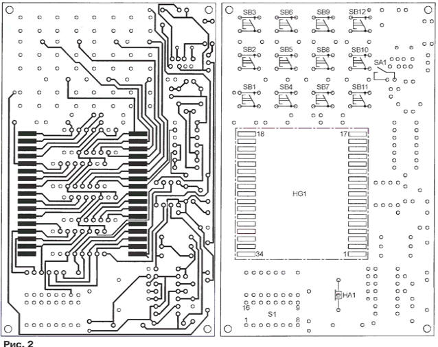
The timer is assembled on a two-sided printed circuit Board. In Fig. 2 shows by her side, on hosting the indicator HG1, buttons SB1 - SB12 (TS-A3PS-130 or equivalent) the switch SA1 and sonic emitter HA1. All other elements are mounted on the reverse side shown in Fig. 3, and the battery GB1 (three galvanic size AA) - in a container outside of the Board.
Instead PIC12C508A microcontroller will fit without changing the program part no pic12c508, PIC12C509 or PIC12C509A. Relay K1 - RAS, the performance of the RS4.569.435-04 or RS4.569.435-09. Quartz resonator ZQ1 - in compact cylindrical body. Note that the resonators are large in size do not work well in low supply voltage.
When establishing the unit fixed resistors R8 temporarily replace variables the value of 100 kω and choose the frequency of the sound signal the maximum volume. Measuring entered the resistance of the variable resistor, install instead the nearest permanent value. For stable operation crystal oscillator in the interval of changes of the supply voltage can to require the selection of resistor R5.
Author: A. Ermakov, Nizhniy Novgorod