


")

This timer is convenient to use where there is no sustainable supply. It helps conserve battery power, since immediately after the end of a predetermined time delay, the timer automatically returns to the standby mode. The countdown of the time interval is accompanied by "ticking" that informs about normal the functioning of the device.
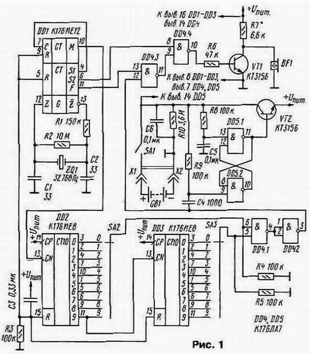
The timer provides a countdown time from 1 to 99 min. Its principal the scheme is shown in Fig. 1.
(click to enlarge)
The device consists of a host of countdown, elements sound alarm and disconnect device. In the node timing includes crystal oscillator with a frequency divider chip DD1, two decade decimal counter on chips DD2. DD3 and the chain on the initial installation the elements R3, C3.
Consider the work timer. On closure of switch SA1 the voltage is delivered to the trigger on the elements DD5.1, DD5.2. which for by connecting capacitor C5 to the input is set to the position log. 1. This opens the transistor VT2. power is supplied to the chip DD1 - DD4 and starts counting down the time set switches SA3 (tens of minutes) and SA2 (units of minutes). Thus on the pin. 12 chips DD4 will be the level of the log. 0, and on the pin. 11 - level of the log. 1. Through the element DD4.4 to the base of transistor VT1 pass a pulse frequency of 2 Hz with a pin. 6 DD1 chip. These pulses have the form of a meander, so the emitter BF1 connected to the collector of transistor VT1, makes clicks with a frequency of 4 Hz. perceived as a characteristic "ticking".
At the end of the time delay on both the movable contacts of the switches SA3 and SA2. and then on the pin. 3 element DD4.2 and the pin. 12 element DD4.3 IC DD4 level appears log. 1. Element DD4.3 passes the signal frequency of 1024 Hz. Through the element DD4.4 and the transistor VT1 he goes to the emitter, which is starts to produce an intermittent tone signals. The alarm continues for one minute, after which the negative differential output voltage element DD4.2 through the differentiating circuit C4R9 switches the trigger on the elements DD5.1. DD5.2. Transistor VT2 is closed, removing the power from the node timing and elements of the audible alarm. The timer enters the normal mode. Current. consumed in this mode is approximately 4 μa. For re-start the timer should switch SA1 off the power and after few seconds again to turn it on.
In the Assembly of the timer used resistors KIM (R2) and CMP-0.125 (the rest). Chip KIE and CLA similar interchangeable series C, 564. The resonator ZQ1 can be anything at 32768 Hz even with the variation in frequency of several Hertz from the specified nominal value. System, another suitable, but in this if you can decrease the Audio volume. The switches SA2, SA3 - PP10, SA1 - any compact. In the absence of drum switches PP10 valid replace them with the disk or button with P2K vzaimovlijanie. To power the device can use the battery "Corundum" and its foreign counterparts. The efficiency of the device is retained when the voltage to 6 V.
The details of the timer are mounted on a circuit Board made of fiberglass dimensions 65x52 mm (Fig. 2). On the same Board set the switches SA2 and SA3 and the emitter BF1. Last fixed by printed conductors in parallel circuit Board and insulated from it by a strip of thick cardboard.
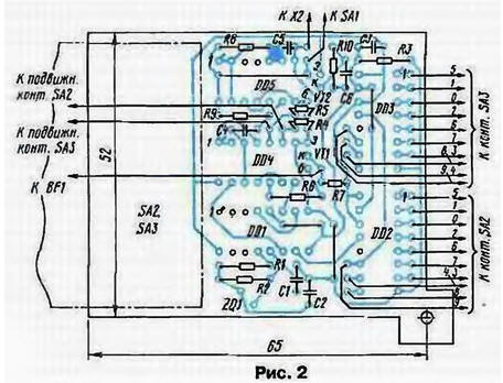
Body shoulders SN-3 are soldered in convenient locations to track the common wire. The unused inputs of the chip DD5 connected to its output 14.
The housing of the timer is made of foil fiberglass. The dimensions of the walls selected depending on the dimensions boards and switches. Inside the case you need to provide the compartment with a removable cover to accommodate the battery. Front side switches (drums and box numbers), and the switch SA1 displayed on the front panel of the device. In one of the side walls made holes opposite emitter BF1.
The timer is assembled from serviceable items, should work instantly. If after power-clicks the system will not verify that the delivery the supply voltage on chip DD1 - DD4. and then work quartz generator. In the absence of generation may require selection of one of capacitors CI, C2, or both. The desired volume of clicks of the system set selection resistor R7.
To change the time of sounding of a tone at the end of the exposure can be to use the standby multivibrator, made two free items chip DD5 (not shown).
The resistor R6 and the transistor VT1 can be excluded by connecting the emitter to the output element DD4.4 directly or through a resistor R7.
Author: Dmitry Nikishin, Kaluga