The hostess puts the dish in the oven and remembers it only when out of the oven the smoke... this situation is familiar to many. To avoid it will help the timer which after some time sounds the alarm, warning that the dish in the oven needs attention.
The main advantage of the proposed kitchen timer is easy to use. While the plug is inserted in the socket 220, the device is ready for use, enough click on the button. On indicators at any time, you can see how much time left before the end of exposure. At the end a beep is heard smoothly increasing the volume, after which the timer will automatically turn off, waiting for new team. The plug may be left plugged in constantly, as in the passive state (before the exposure and after the beep) almost all nodes of the timer is de-energized. At this time, current is consumed only transformer no-load power.
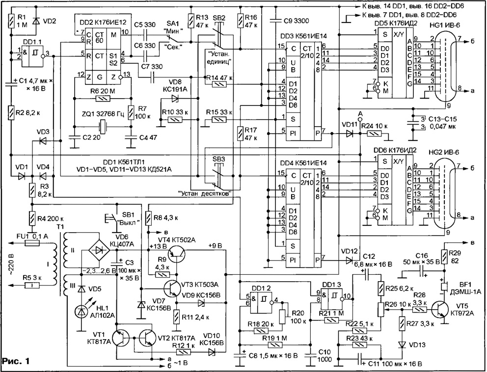
Schematic diagram of the timer shown in Fig. 1.

(click to enlarge)
The oscillator is assembled by the model scheme on a chip CIE (DD2) with a quartz resonator frequency ZQ1 32768 Hz. Its pulses (with a period of 1 s or 1 min, depending on the situation switch SA1) arrive at the node timing - counters DD3 and DD4 CIE. They are included so that you are working on subtraction, so the shutter speed and the time will go downwards. Elements DD5, DD6, HG1, HG2 designed to decode and display the remaining time.
To the outputs of the transfer counters DD3 and DD4 is connected to the element of coincidence of diodes VD11, VD12 and resistor R24. A logic low at its output serves as signal the end of the exposure. The differentiating circuit R1C1 and threshold element the Schmitt trigger-tbDDI.1 - create the momentum during which the audible signal.
The element DD1.3 - generator audio signal, the transistor VT5 - it amplifier. Sound frequency modulated pulses of triangular shape, flowing through the resistor R19 with the generator on the DDI element.2-It gives the signal more visible, vibrant character. A trimming resistor R20 the frequency of the "vibrato" can be changed.
Due to the circuit R23R27VD13C11 at the time of triggering of the timer alarm sounds with low volume, which as the charging of the capacitor C11 smoothly growing. Variable resistor R26 set the maximum volume signal.
The host power timer transformer T1. The voltage from winding it up II, rectified by a diode bridge VD6, is fed to the stabilizer (transistors VT3, VT4). The voltage drop across the led HL1 and diode VD5, through which the direct direction flows the load current of the rectifier increases by 2.3 2.6 In... the potential difference between the cathodes and the anodes of indicators HG1 and HG2, leads to a marked increase in the brightness of generated numbers.
AC filament voltage indicators comes from winding 111 of the transformer T1. When the timer is in the passive state, the electronic key on transistors VT1 and VT2 breaks the heating circuit. The AC voltage drop on open during exposure of the key does not exceed 0.15...0.2. So when rated for indicators IV-6 filament voltage 1 To voltage in the winding III the transformer T1 must be equal to 1.2 V.
When the timer is enabled in the network, but is in passive mode, all nodes works only rectifier diode bridge VD6. Reference voltage on the basis transistor VT3 is not, therefore, the transistors VT3 and VT4 are closed and the voltage in the circuit +9 V is missing. The key VT1VT2 is open, so as to open the transistors it is necessary that the voltage +9 V exceeds the voltage stabilization the Zener diode VD10.
When you press any of the buttons SB2 "Set. units" or SB3 "Set. dozen" the voltage of the capacitor C3 of the filter of the rectifier through a resistor R8 comes on Zener diode VD8, limiting at approximately 9 V. the chain VD3R3 voltage is applied to the base of transistor VT3, opens it and leads the stabilizer in action. A voltage of +9 V is supplied to all nodes of the timer, and the key VT1VT2 includes the intensity of the indicators.
In the future (after you release the buttons SB2, SB3), the voltage in the circuit formation exemplary voltage stabilizer is present thanks to the diodes VD1 and VD4. Their the anodes are connected to such points of the timer, that during the whole exposure period and signal voltage by at least one of them has a high logic level. At the end of exposure and the signal levels in both points become low, exemplary voltage on the base of the transistor VT3 is reduced to nearly zero and the timer goes into a passive state. While you can force the shutter speed bring it in this state, pressing the button SB1 "Off".
At the moment of switching voltage of +9 In the circuit C9R15 generates a short pulse, recording in the counter units DD3 code figures 9 (it is set to the appropriate connecting the inputs D1-D8), and a counter dozens DD4 - code zero. These figures appear on the indicators, and if pressed immediately let go, the timer will practice restraint in 9 minutes or seconds (depending on the situation switch SA1). But if the button SB2 or SB3 hold, pulses a frequency of 2 Hz is received at the clock input of a corresponding counter (or DD3 DD4), reducing on 1 its contents with each pulse.
So at pin 10 of the chip DD2 momentum appeared after exactly 60 seconds after the end time setting (release buttons), the seconds counter chip DD2 blocked high logic level received at its conclusion 9 with the Zener diode VD8, until at least one of the buttons is pressed.
After releasing the buttons the clock input of the counter DD3 through the switch SA1 is connected to the output of the minute or second impulses of the chip DD2, and the clock input of the counter DD4 - output transfer counter DD3. Countdown is running the exposure time. After the contents of both counters will be zero, their outputs transfer (findings 7) at the same time appears a low level, the diodes VD11, VD12 will be closed and will begin charging the capacitor C1 in the circuit R1R2R24. A high level at the exit of the element DD1.1 will allow the sound generator signal. Approximately 5 capacitor C1 is charged up to the changeover element DD1.1, a high level output which changes low that stop beep and turn the timer to the passive state. The signal from the exit of the element DD1.1 comes on the pin 5 of the chip DD2, barring her work. Otherwise "used" the range of shutter speeds counters DD3, DD4 can change condition at the alarm time, which will lead to a crash.
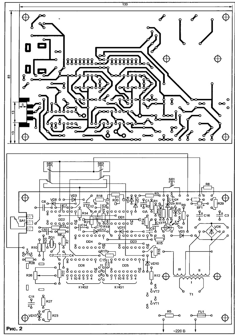
The printed circuit Board of the timer shown in Fig. 2, made of one-sided foil fiberglass.

(click to enlarge)
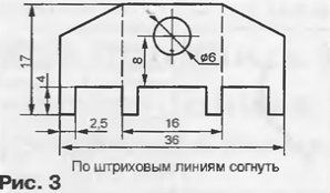
Conclusions and housing slide switch PD-9 (SA1) soldered directly to the pads. Fixed resistors - MLT, S2-33 or import specified on the scheme of power. Trimmer resistor R20 - GPA-16, SDR-38A or SDR-38V, instead it may be pre-set selected fixed resistors. Variable resistor R26 - JS4-1 or GPA-6A. It mounted on the U-shaped bracket made of sheet brass or steel with a thickness of 0.5 to 0.8 mm. Sweep bracket - Fig. 3. If you do need to adjust the volume no, variable resistor R26 is also possible to replace the selected constant.

All oxide capacitors - C50-6, K50-16, K53-35 or K53-1A, rest ceramic km, KD or imported. Diodes KDA can be replaced with any KD522 letter index. Two or three similar diode connected in series, replace the led HL1.
Transistors VT1, VT2 - CT with any letter index and ratio h21e not less than 80. Transistors VT3, VT4 must have h21e not less than 60 (here come and the series transistors KT315, KT361). A composite transistor KTA can be replaced normal CT with any letter index (h21e - at least 100), and in the circuit its emitter is necessary to include in the forward direction of the diode series or KD521 KD522.
The power transformer T1 - TP-321. Using quite a big gap between his secondary (according to scheme II timer) winding and the magnetic core, at the same the frame is additionally wound around the winding III - 38 turns of wire PELSHO 0,31 0,25...mm. If the HG1, HG2 not applied IV-6, and others semielemental luminescent indicators (IV-3, IV -, IV-22), number of turns winding III need to change so to get the required voltage Nacala. Instead of the above transformer it is possible to use other suitable for overall power (not less than 3 watts) with secondary windings on 12...18 In (II) and 1.2 In (III) or allowing to wind such coils. The transformer preferably select from having a separate standalone the section of the frame to the secondary winding. This will provide the necessary electrical safety timer.
Resistor R5 reduces the idle current is constantly plugged in transformer, reduce heat and improve reliability [1]. Specified in the scheme Fig. 1 the value and power of the optimal resistor for transformer TP-321, the current idling to no more than 5.. .7 mA. With transformer, no-load current stroke which is greater than 10 mA, you can use a resistor MLT-2 par value 1,2... 1.5 Ohm, but better - reactive ballast resistance, which will reduce the allocation of heat. This well-suited relay coil PCM, RES, RES working on voltage of 24 V. the Armature of the relay must be locked in extended to the magnetic circuit position.
Charge timer is placed in a plastic housing with a closed green glass window for indicators. Button SB1 - KM1-I SB2, SB3 - KM2-I, a sound emitter BF1 - DAMS-1A. They are fixed to the housing and to the circuit Board connecting flexible wires. When used as BF1 piezo oscillator of SN-1 in parallel it is necessary connect the resistor of 4.3 kω, placing it in the provided on-Board hole. In Fig. 2 this resistor is shown by a dotted line.
First, it is recommended to mount the transformer T1, a diode bridge VD6, the capacitor C3 and the details of the voltage regulator. To check for the exit stabilizer temporarily connect a dummy load resistor MLT-1 resistance...560 470 Ohms, and between the base of the transistor VT3 and positive the output capacitor C3, the resistor MLT-0,25 nominal of 15...18 ohms. Output the voltage must be within 9...At 9.5 V. it can change a little, setting other instances the Zener diodes VD7 and VD9.
To first activate the timer in the network is a good idea to clip on his Board at the transformer T1 from the printed conductors plate of insulating material size 47x35 mm (for example, attaching it with screws fixing transformer). The plate should close all the conductors and conclusions elements associated with network 220 V. the Resistor R5 and FU1 fuse-link is also desirable well isolated. This will allow to check and adjust the timer without fear electric shock.
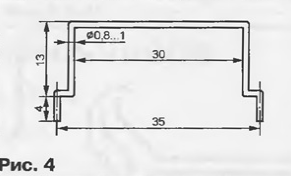
Check the operation of the stabilizer, you can remove temporarily installed the resistors and to continue the installation. Better to start with jumper wires, because some of in the future will be under the chips. One of the webs allocated to Fig. 2 bold line not only serves as the connecting wire, but element attachment indicators IV-6. The dimensions shown in Fig. 4, is selected based on the height of the transformer TP-321 and diameter of cylinders of indicators. This jumper better to mount after DD1 chip, but to install indicators. Their feature parallel to the Board so that the upper part of the cylinders can had to be attached to the jumper using yarn and glue.

Installing all the parts and visually checked for proper installation, verify the absence of a fault in the power circuits, "prozvoniv" them with an ohmmeter. Correctly assembled the timer starts immediately after switching on the network and pressing one button SB2 or SB3 - lit numbers on the indicators, there's a countdown time. Otherwise you have to check the voltage of the chips (9 In) and AC filament voltage indicators (0,95 1,05...). If timer operation there are no pulses at the outputs of the chip DD2 or frequency their sequence is different from the nominal, the most common cause of the malfunction quartz resonator. If a large exposure precision is not needed, you to do, replacing the RC-circuit as proposed in [2].
The timer is suitable not only for sound but also for inclusion on given time any loads, such as heater or fan. Of course, this will require an electronic key or relay corresponding power. The control key signal will serve as the point a (see Fig. 1). To unfortunately, the load capacity of the output is small. More powerful signal voltage 9 V directly from the output of the stabilizer. But keep in mind, it duration greater than a predetermined shutter speed on the playing time of the audio signal.
Please note that on the PCB (see Fig. 2) the unused inputs element DD1 chip is connected to the point A. Therefore, the output referred element (pin 11 DD1) during the delay countdown - log. 0, when the alarm signal - log. 1, and in the passive state of the timer it is the high impedance state.
Set the shutter speed as follows. When you press any of the buttons or SB2 SB3 timer is enabled (unless, of course, the plug is inserted in the socket) and the display will show the number 09. If you press and hold, for example, buttons SB2 digit in the ones place twice per second is reduced by 1 (9, 8, 7,..., 1, 0, 9,...). If I press the button "Set. dozen" with the same frequency are replaced by digits in the tens digit(9, 0, 18, 9, 0...). Thus, you can set any shutter speed in the range of 0-99 minutes or seconds. Unit of reference is chosen with switch SA1. Automatic delay countdown starts from the time you release buttons.
Remembering the selected shutter speed is not provided. Therefore every time ask again. The order of pressing the buttons setup in most cases indifferent. However, to avoid failures, it is not recommended to press the button SB3 "No. dozens, if in the ones place is zero. Should first ask any non-zero number of units followed by the corresponding number of tens and then - zero units.
Literature
Author: Andreev, Togliatti


