This Board device designed to measure the frequency of rotation of the crankshaft shaft gasoline four-stroke internal combustion engine (main mode) and display the current time (additional mode). The display unit shows the speed with increments of 1 min-1 and seconds, minutes and hours. Eats tachometer from the onboard network of the car and consumes a current of about 0.012 A.
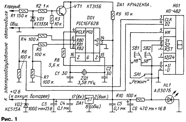
Schematic diagram of the tachometer shown in Fig. 1. The basis of the device - the microcontroller DD1 PIC16F628 Microchip. You can also use and other microcontroller this company, but will need some minor adjustments programs and fees. Other nodes of the device: the input pulse shaper (the resistors R1-R3, a Zener diode VD1 and the transistor VT1); a voltage regulator (Zener diode VD2, capacitors C3 - C6, DA1 chip); LCD indicator (HG1); the voltage divider resistor R10 and the led for HL1 power indicator HG1 (about 1.7 V); controls: power switch SA1 "Mode" to select the mode of operation of the device ("Tachometer" - "the Hours") and buttons SB1 "HB" to set the time and SB2 "HC" to set the time in clock mode.

The controller is reset automatically when you turn on power. When a high level input on the controller is in operating mode The program also provides automatic transfer controller original state when hovering, which uses the built-in watchdog timer.
The device is applied desethylatrazine LCD module - indicator, equipped with a controller NT company Holtek serial download information on line DI and synchronization on the CLK line. Information is fed to the input DI (pin 4), it is fixed on the falling edge of a clock pulse at the input CLK (pin 3).
The module is a printed circuit Board dimensions 67x36 mm, which placed the actual indicator and controller. The dimensions of the visible indicator fields - 35x12 mm character height 10 mm. power supply module is 1.2...1.7 V, current consumption is not more than 10 μa.
In addition to the function indicating the measured value of the rotational speed, the module performs function clock and timer with output this information to the indicator in real time. For operation of the tachometer input NC (pin 5) of the module should to connect with the common wire, and the inputs S1, RST and S2 (pins 6-8) to leave free.
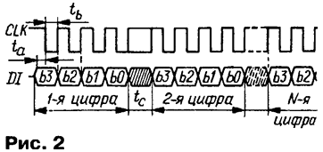
The indicator can display 16 different characters, each of which is encoded four-digit binary number. While loading the module the first of them he appears in the rightmost position of the scoreboard. When loading the second symbol of the first move to the left, etc.
The time chart load character codes in the indicator shown in Fig. 2. Minimum time parameters: ta=1 MS, t=2 µs, tc=5 μs. For a full update of the indicator requires about 170 μs. The period update the displayed information should not choose a smaller one second.

In a vehicle equipped with a standard ignition system, the input of the tachometer connected to the primary winding of the ignition coil. If the breaker is built on the Hall sensor, the tachometer input connected to the output of the sensor (usually to his the middle pin). It is also possible the input through the capacitive sensor, mounted on the high voltage output of the ignition coil. Power wires tachometer is best to connect directly to the battery.
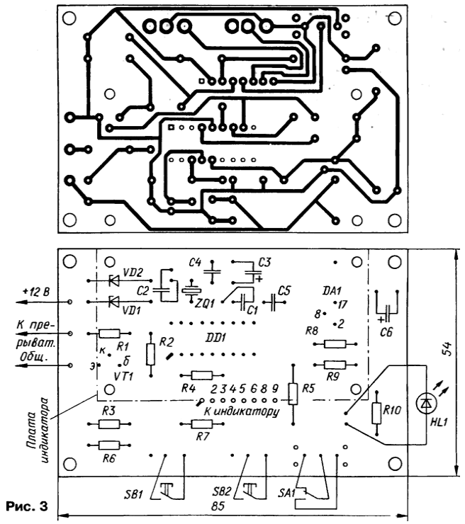
All the details of the tachometer, but the indicator, mounted on a unilateral the PCB size 85x54 mm foil fiberglass with a thickness of 1 mm. the Drawing Board is presented in Fig. 3. The fee module of the indicator is connected to Board tachometer short flexible insulated wires. Cost of the module can to attach on the racks parallel to the main Board (it provides a corresponding mounting holes) or at an angle.

(click to enlarge)
The tachometer is not critical to the choice of parts used. Resistors and capacitors can to have a tolerance of ±10 %. A voltage regulator CREA (good and CREW or import 7805) to the heat sink is not needed. Transistor KT315B can be replaced KT3102 with any letter index, a Zener diode XA - XA and XA - on CSA or other, for a voltage 15... 19 In (you can also apply special automotive varistor SIOV S10K14AUTO Siemens Matsushita Components).
Led ALB or ALBM (good only for "red"!), working low voltage stabistor, replace stabilogram XA (and CSA), but resistor R10 will need to choose the operating current stabilization. Capacitors C1, C2, C4 and C5 - km-5, km-6; C3, C6 - oxide import. Resistors - MLT, S2-33. The switch SA1 - PD9-2; buttons SB1, SB2 - MP. Module-indicator can be replaced by another controller NT
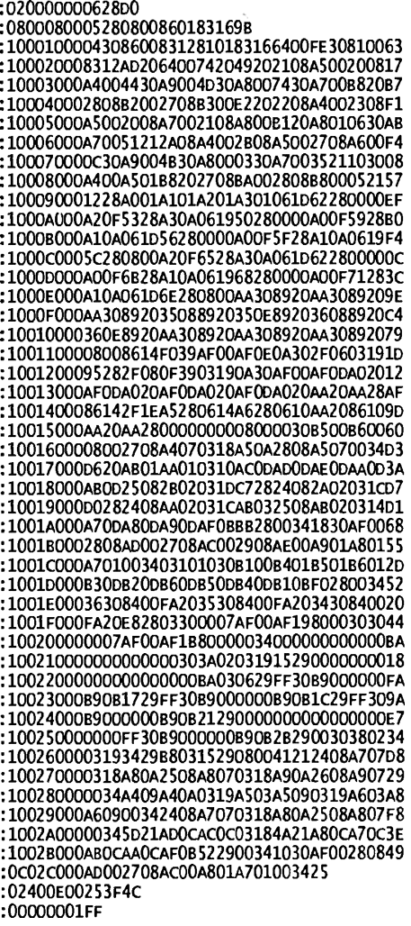
Program in Intel HEX format, which must be entered into the controller DD1, presented in the table.

(click to enlarge)
Correctly assembled from undamaged parts of the instrument in adjustment and does not need begins to work immediately after power-up. The accuracy of the readings depends the frequency of the quartz resonator ZQ1.
Those who want to replicate the design, I recommend you to read publications listed in the bibliography.
The work program of the microcontroller DD1 assembler MPASM V2.50.02
Literature
Author: A. Ulyanov, Velikie Luki, Pskov region.


