Descriptions of designs for automatic switching on and off of lighting according to natural light have been published in various publications, for example [1, 2]. As a switching element in the devices used are either electromagnetic relay or a thyristor.
In the proposed design this function is performed by the triac. Due to the fact that his work does not depend on the polarity of the applied voltage, eliminating the need for powerful depolymerize the rectifier. This allows to simplify the design of the machine and to reduce its dimensions. The proposed device for driving light sources with a total capacity of 400 watts.
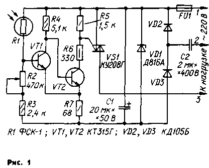
Photosensor (Fig. 1) consists of a sensor (R1), threshold device, is the scheme of the Schmitt trigger (VT, VT2), and a switching element (VS1).

Photoresistor R1 together with resistors R2 and R3 form a voltage divider, which determines the base current of the transistor VT1. In the daytime, when the photoresistor is illuminated, its resistance is relatively small, therefore, the transistor VT1 is open and saturated, and VT2 is closed. The collector current of the transistor VT2, and hence the current of the control electrode of the triac is practically zero. The triac is thus closed and the current through the load flows.
With the decrease in light resistance of the photoresistor increases and the base current of the transistor VT1 starts to decrease. When reaching a certain value of the VT1 transistor comes out of saturation and begins to close. The increasing voltage drop across the resistor R7 accelerates the closing of the transistor VT1 and opening VT2.
Current control electrode of the triac, which flows through the open transistor VT2 and resistors R6, R7, supports triac open during both half-cycles of the mains voltage. Consequently, the lamp immediately begin to Shine at full intensity. The process of turning off the relay in the reverse order.
The threshold photoelectric install a variable resistor R2 and the resistor R3 serves to limit the current of the divider in contact with the photodetector direct sunlight. Resistor R6 determines the current of the control electrode of the triac, which is open when the transistor VT2 must be greater than the current inclusion of the triac, but smaller than the maximum allowable collector current of the transistor VT2. Resistor R5 equalizes the voltage on the control electrode and the cathode of the triac, when the transistor VT2 is closed. This ensures reliable switching off of the triac and the immunity photosensor in General.
In the device used fixed resistors MLT, rigged - SP2-3. The capacitor C1 is any compact, C2 - MBGO-2. Transistors VT1 and VТ2 - CTG or CTE with the current transfer ratio of not less than 60.
The device is assembled in a round plastic splitting box designed for outdoor wiring. All the components are mounted on a circular printed circuit Board from one-sided foil fiberglass 1.5 mm thick. The drawing Board and the arrangement of parts therein shown in Fig. 2. Resistor R5 soldered directly to the terminals of the triac and resistor R6 between the output of the gate electrode and the printed circuit Board.
The cathode of the Zener diode VD1 and the triac are connected among themselves and with the Board mounted conductor. Screw terminals of the anode, these parts should be trimmed so that they do not protrude beyond the mounting nuts. Photoresistor their findings are inserted into and soldered to charge a tubular rack with a height of 25 mm so that it will free space for mounting other parts. As racks used socket of the appropriate diameter of pin connectors.
Wire network and the load circuit is attached to the screw-type terminal, similar to those used in telephone handsets. Clips soldered to the Board in four points each. The junction box should be selected with bright translucent cover, so as not to cut a special window for the photoresistor.
The device is assembled accurately and out of the elements specified in the scheme hyponomeuta, in the establishment does not need, it is only necessary to set the threshold. Mount the relay in such a position that light from the lamps, manages, falling on the photodetector. To avoid getting into a box of water and foreign material inlet it should be pointing down, and the cover after the installation is sealed with a waterproof varnish or glue.
Attention! It must be remembered that all the elements of the device are at mains voltage, so when repairs and adjustments should strictly observe the safety regulations.
Literature
1. Macedonia V. the Machine "key" lighting.- Radio, 1974, No. 9, p. 53.
2. Borovsky V. P" Kostenko V. I., Mikhailenko V. M., Partal O. N. Reference circuitry for radio Amateurs.- K.: Tekhnika, 1987, p. 113. Radio 6/89
Authors: A. Ivashchenko, N. Kotelenez, Chernigov; Publication: N. Bolshakov, rf.atnn.ru


