


")

There are times when you want to control the equipment (TVs, the VCR) for a particular program without operator intervention. This may be necessary, for example, in video surveillance systems. Normal universal storage consoles for radio equipment of little use here, since it requires specific sequence of actions which depends on the external control signal. The proposed device performs this task.
In recent years, the range of household video equipment (TV, VCR) added new devices - door videoplace, surveillance cameras of area or object, etc. Hence the need for a device, able to manage for a given program on-off device, and preferably without any modification. One of the variants of this device are presented below.
It is intended for remote control of household television and video equipment in the systems of observation. With this device you can automatically turn on the TV and VCR, this will simplify the use of the eye and hidden cameras, and will save you from having to buy a monitor.
"CYCLOPS" is a small device with a digital display, three buttons having the side window of the IR receiver and external IR emitter. The device can be placed in any convenient position for the user, and an IR emitter attached to the wall or furniture in front of the TV and the VCR.
The scheme of the device depicted in Fig. 1.
(click to enlarge)
Let's start with a brief description of the principle command remote controls for home appliances. There is several ways of encoding information for transmission over the IR channel. First - high-frequency modulation. Relatively low-frequency information parcel modulate a carrier frequency close to a 43.5 kHz. This allows you to get rid of the constant component of the infrared background of the room. The second way - the team present in the form of a code, "MANCHESTER", which has zero long or a single state and therefore well protected against interference. Some manufacturers for a more economical expenditure of battery power remote control and method of applying a single code transmission. When you press the remote first, the parcel is passed with the command code, followed by a relatively short parcel ID hold down the key.
The task of the device to receive and decode commands, write them non-volatile memory, and then, having received a signal from the outside, to broadcast these the commands in sequence. The quality of the work depends largely on accuracy of reception of commands.
Module BL1 - standard single-chip photodetector from color TV - designed to input commands from the remote control. From the output of the module purified from the constant component invertirovannye digital sequence goes to input P3.2 microcontroller DD1.
The photodetector is better to use ready, as this device to it charged pretty high standards. Photodetectors of different types have now on sale in stores.
Processed information about the accepted commands in a special form enters storage in the ROM DS1. Generated code sequence output from the P1.0 controller DD1 is input to the element DD2.4, which is paired with DD2.3 forms a pulse generator with a repetition period of 27.2 μs. This option you must endure as accurately as possible, since most single-chip photodetectors, household apparatus for receiving commands from remote control unified and have the same parameters carrier frequency.
From the output of the element DD2.4 the code sequence fed to the current amplifier - transistor VT2. Load transistor are two IR diode emitter BI1 and BI2. They operate most video equipment. Diodes of various types - ALA and ALA - not chosen by chance. The fact that the emission wavelength of remotes SDU different television and video equipment from different manufacturers can vary. So used two different diode, to obtain a wider spectrum of radiation. If power is not enough (that's what happens when equipment is located in different places), you can increase the number of LEDs, picking up resistor R15.
Device "CYCLOPS" has two universal inputs. Input 1 - plated the isolation optocouplers U1 is designed for an input DC voltage of 12 V, but if connected via the quenching capacitor, then we can work from the mains ~220 In (for example, connect the bell housing). Input 2 is the input of the Schmitt trigger, collected on the VT1 transistor and the element DD2.2. This input can be submitted and 12 In, and any analog signal from the microphone amplifier or Audiodamage.
The signals from both inputs pass through a digital filter, the transmission coefficient which install software. Both inputs can operate from any the pulse front, which allows ispolzovat device with various sensors.
The device is assembled on a printed circuit Board (Fig. 2) of one-sided foil fiberglass thickness of 1.5 mm. the Resistors R17-R32 - R1-12 or for other surface mount (they are soldered to the circuit Board by conductors). If the resistors are surface mount, you can drill holes and install vertically normal MLT 0,125. Digital led indicator HG1 (King Bright) soldered to the circuit Board by printing on top of the resistors R23, R24, R31, R32. It is also points up. The control buttons also side printing. Stabilizer DA1 screwed to the Board, under foil it performs the function of a heat sink.
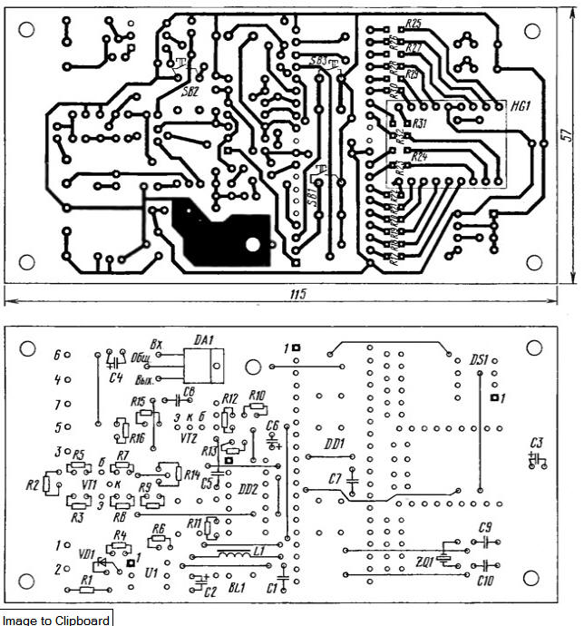
(click to enlarge)
The program is written with the expectation that the frequency of the master clock is 24 MHz. Can, incidentally, use Quartey resonator to another frequency of 10 MHz and more. IR photodetector BL1 - from televisions and VCR Funai, Samsung, LG. The inductor L1 - DM-0,1. The microcontroller DD1 (ATMEL) installed in soldered to the motherboard panel.
When programming the device for the connection cables must be possible in short, to reduce the effect of interference. The window of the photodetector, it is desirable to close an optical filter that transmits only infrared rays. Remote control should be placed at a distance of 10…60 cm from the device. In the memory device enter the commands from the remote control of the TV or recorder. On command from external sensor call button, the device will execute the specified program: will include or turn the TV and VCR.
In control panel there are three buttons and the display. Buttons user can choose different options. The device memory is divided into 16 sections (programs), each of which can consist of 16 steps (commands equipment).
For normal and efficient operation of the device in video surveillance system it is necessary to introduce the program into memory. To better understand the principle programming, let us consider an example. For example, the doorbell rings required turn on the TV for 15 sec, then off, and the VCR to turn on the entry within 30 seconds and then turn off. Because some TVs do not immediately after power is able to accept commands from the remote control must be maintained pause at 5 before turning on the TV video input (AV), which is connected video-eye.
Imagine how you can perform these operations with the TV and remotes VCR.
Now try to translate the control algorithm in the program for the device "CYCLOPS".
Care should be taken to compile the program. Considered the example does not take into account all the peculiarities of the system of observation, and household equipment often working on different algorithms with different reaction times.
The device has five modes of operation.
MODE PROGRAM - PROGRAMMING
Mode "PROGRAM" include clicking on the button SB1 "Mode". The display will flash '00 (point, standing in front, indicates the inclusion of programming). If programs have already been introduced and some of them need to be corrected, it is chosen buttons SB2 "<<<" or SB3 ">>>".
The symbol in the first character of the Board - room of the program is dialing in hex code (0 - first, F - sixteenth), and the second sequence the step number (command) in the program in hexadecimal code.
Pay attention to the type of remote control. The fact is that in the systems of control used several types of commands. Differences in working with TV or VCR can be quite evident, however, in the device "CYCLOPS" these commands are entered differently. For simple commands (without power saving) it's simple: one click - one team. When you enter commands another species will need to do three presses on the same button of the remote, to CYCLOPS realized a piped command. The difference will be seen immediately on the job device. While the team has not been reliably determined, the next step is not will!
Defining the command, the device switches to the next program step is the number in the display will increase by one. Now you can enter time pause between commands or the following command. The pause time dial buttons "<<<" or "> > > " you may want to change from 1 to 256 C. Each press adds latency at 1 s, the total time, in seconds, the display is in hexadecimal code. After each click on these buttons, the display for about one seconds indicates the length of the delay that will be executed only AFTER what a given team. By default it has the minimum possible value is 1C.
After all the steps of the program by clicking on the button SB1 "Mode" can be interrupted programming and buttons SB2 and SB3 to choose to enter the following program. Repeated pressing of the Mode button will cause the device to go into "WORK" (about this will be discussed below).
If the programming command is entered, already introduced previously, it is not given a separate place in memory, and the program is placed. To distinguish primary and re-introduction of any command as follows: when the primary input when the device does not identify it with any of the teams already available in the memory, the indicator displays the point in the second display familiarity ('0'0) and remains until you release the button; in the same case, if the input command the device finds among already stored in memory, a point in the second familiarity does not appear.
This feature is useful for determining reliability of the code capture device. If you repeatedly enter the same command, and all attempts or some of them, except the first, are accompanied by the appearance of the point in the second familiarity, means, code is determined uncertainly. You should choose the distance between the device and the remote or get rid of excessive infrared background the apartment (say, the curtains drawn, if the court of the sun is shining bright).
Here it is worth noting that sometimes there are remotes that when you press one and the same button twice will generate codes that are slightly different from one another. For example, the remote one of the TVs from SAMSUNG at every odd-numbered pressing gave the last bit equal to one, while each even this bit was is equal to zero. On the device this feature is not affected.
THE "TEST"MODE
The "TEST" mode is intended for debugging and verification of programs. It consists of two sections: verification of commands and programs. To enter these modes can mode programming.
By pressing simultaneously the buttons SB2 and SB1, the display will show L0. The Symbol L means testing team, and the digit 0 indicates her room first. Choose check the command buttons SB2 and SB3. When you press the SB1 button the unit will then play the selected command.
By pressing simultaneously the buttons SB3 and SB1, the display will show NO. In this mode you can check the whole program. To choose the program can check the buttons SB2 and SB3. When you press the SB1 device plays the selected program. Thus it is possible to check the work of each individual team and the program as a whole. In the event of malfunction of at least one team must more closely to reprogram the device.
When it detects an error in the program you can return to at mode PROGRAM and reprogram.
To exit "TEST" mode, if again click on the same buttons that were pressed at the entrance.
MODE "WORK"
Mode "WORK" is a major. The user can select a programme number, stored in the memory at which the device will work.
Examples of the display in a mode "WORK": flashing 10 characters or 3 - or 04. This is a standby pulse from any input. The first digit shows the number the program, which will run from the entrance 1 and the second digit is the number the program, which will run from the entrance 2. If instead of the numeral display highlights the dash, it means that the corresponding input is disabled and the device will not react on impulse. When the display is flashing two dashes - disabled both inputs and CYCLOPS will not perform any program. Choose the program for each input can be the SB2 and SB3.
If within a certain time of the pulse to the input is not received, the display turns off and the device continues to operate in the mode of "WORK" without indication. This function is needed to ensure that the display did not attract undue attention. The inclusion display can be accessed by clicking on the button SB2 or SB3. The time interval to the turning off the display is set in the device settings.
MODE "ACTIVE"
If the device is in "WORK" and to any of its inputs, for which the program, receives a pulse, it switches to "ACTIVE". The pulse duration must exceed some value (parameter P0 or P1 in the settings section). This is necessary to prevent false triggering of the device from short pulses that may occur as a result of penetration of interference. Immediately after switching the mode to "ACTIVE" CYCLOPS begins to execute the program, specific for a given input. The display highlights the special character in the form three horizontal lines and the number of the command that is transmitted. At this time the device is not capable of perceiving clicking on the button or repeated pulses at input. When you are finished run the program, the device will return to the "WORK".
MODE "PARAMETER"
This mode is required only during programming of the device. Sign in from programming mode by simultaneously pressing the button SB2 and SB3.
We list the parameters that can be set in this mode.
- P0 - guard interval of the 1st channel (0 - FF) (1/100 sec).
- R1 - guard interval of the 2nd channel (0-FF) (1/100 sec).
- P2 - the number of packages in the pack (2-32).
- RZ - interval between samples (40-95 %).
- P4 - frequency of the quartz resonator, MHz.
- R5 - <reserved>.
- R6 - program number 1 sign.
- P7 - the program number of the 2nd entrance.
- R8 - time to extinguish the indicator, p
- H - each team.
- HX - each program.
The parameters RO and R1 are specified in hundredths of a second and, accordingly, may to take values from 0.01 to 2.56 s. the Task of the parameters RO or R1 is equal to zero permits operation of the device according to the first signal level changes. The active level of the inputs is a level opposite to that which there was input at the time the device goes into "WORK". If you want to input 2 to apply an alternating voltage of frequency 50 Hz, then the parameter P1 must be set equal to zero, as this input will produce a pulsating DC 50 Hz and a duration of less than 0.01 C.
Parameter P2 specifies the number of parcels code team when the device each program step. This option is useful in situations where a managed object (TV or VCR) insecure perceives send commands. Normally a value of 2-3.
The meaning of parameter P3 - the interval between transmissions of commands in the stack, expressed in the percentage of the length of the command (its duration in time). He entered on just in case, so as to "brand" the interval between the commands from the remote control cannot measured and stored in the memory. Practice has shown almost complete impaired for this parameter within the specified range of adjustment.
Parameter P4 change and the case of using a quartz resonator with a frequency differs from that indicated on the diagram. This option is used exclusively for properly generate time intervals between commands and protection intervals. Don't forget that the lower the clock frequency, the worse the accuracy of the records and playback commands. The default frequency of the quartz resonator 24 MHz.
The parameters P6 and P7 - reference, they reflect the numbers of programs tied to inputs 1 and 2 respectively. In the mode "PARAMETER," they can't be changed.
Parameter P8 defines the time in seconds between the last press and the display turns off.
In the programming process "CYCLOPS" may indicate errors. Almost all errors reset automatically.
Here is their description:
- E1 - reception error code.
- E2 - too-long code.
- EZ - code is too short.
- E5 - memory overflow.
- E6 - failure memory.
In case of memory overflow device is required to perform the erase operation. You need to enter into "PROGRAM" and press all three buttons. On flashing symbols in the form of three horizontal lines. Hold buttons, you need to wait for the appearance of the dashes, with all the information in memory commands and programs will be erased. The device settings remain but changes.
Software to the microcontroller
Authors: D. Bespyatyh, A. Kolesnikov, Pervouralsk, Sverdlovsk region.