


")

When using electrical appliances (e.g. electric lamp), there is a disadvantage: you want to fall asleep, but we have to stand up and go to the outlet and pull out the plug. The proposed electronic device allows you to control (to include in a job or off) of various household appliances at a distance of just the spoken sounds. Suffice it to say a certain word and please: earned (or paused) radio or television; lit up (or extinguished) electric lamp or Christmas tree garland.
The device consists of a remote and three switches. To manage there are three command words: "light" to turn on the lamp, "color" - to turn on the Christmas lights, and sound - earned to the radio.
Control scheme, containing the filter unit, in which the frequency analysis and the amplitude of the audio signal (spoken word), depicted in figure 1.
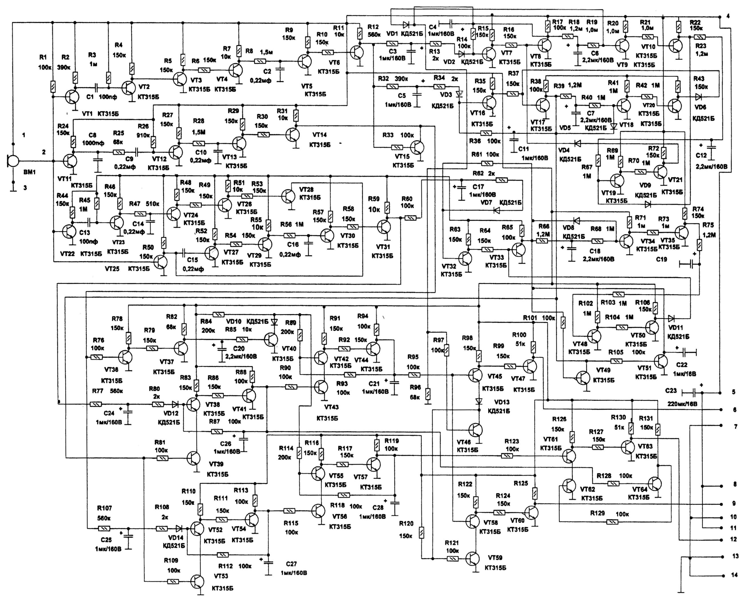
Fig. 1. A circuit diagram of remote control for home instrumentation voice (click to enlarge)
The results of the analysis are transmitted to the memory circuit for comparison with the command words. When they coincide with memory circuits receive control signals for turn on or off lamp, Christmas garlands or radio.
The voice signal from the microphone VM is supplied to bases of transistors VT1, VT11, VT22 VT25 and block filters. Transistors VT2, VT3, VT4 assembled filter the highest frequencies that emit from the speech signal Sizzling sounds of "C, C, z, filtered out high-frequency filter, passing on chain C1 - VT2 - VT3 - R6 - VT4. Additionally, the signal sounds "C, C, z-filtered chain on the transistors VT5 and VT6, the capacitor C2, the resistors R8 - R11. Received a constant voltage equal to the level of the sound signal "C", the chain skips R12 - NW - R13. The signal sounds "C, d, W" to their level voltage passes through chain R32 - C5 - R34. The same signal sounds "C, C, z through a resistor R33 opens the transistor VT15. Received through the diode VD2 to the base of transistor VT7 speech signal of the sound "C" opens it, and the transistor VT8 with closes. Formed on the collector VT8 voltage charges the capacitor C4. Charged capacitor maintains the open state of the transistor VT7, and the transistor VT8 remains closed. The sound signal "C" is received to the base of transistor VТ7, memorized logical element, assembled on transistors VТ7 and VТ8, resistors R14 - R17, capacitor C4 of the memory circuit. The high signal from the collector of transistor \/T8 is double line delays collected on transistors \/T9 VT and 10, the resistors R18 - R22, the capacitor C6, diode VD1 and the transistors VТ19 and VТ21, the resistors R23, R67, R69, R70, R72, the capacitor C12, the diode VD9 and through the diode VD4 comes on the base of transistor VТ8, opening it. In this case, the transistor VТ7 closes. The voltage on the collector will be zero. No signal memorizing the sound of "a".
When entering through the diode VD3 signal sounds of "C" or "z" base VТ16 the transistor opens, and VТ17 closes. This logical circuit element memory transistors VT16, VT17) stores the signal of the sound "C" or "z" at the time passing a high voltage level to the collector of the transistor through VТ17 the delay line transistors VТ18 and VТ20, resistors R39 - R43, the capacitor C7, diode VD5. Through the diode VD6 voltage high-level in doing to the base of transistor VТ17 opens it. In this case, the transistor VT 16 closed. The voltage at the collector of transistor VТ17 will be zero. Not will signal memorizing the sound of "C" or "z".
At the time when the voltage at the collector of the transistor will be VТ8 high level of the sound signal "C", which, passing through resistor R97 to the base of transistor VТ46, open it up. Further, the voltage high level from the collector of transistor VТ17 through resistor R105 opens transistor VТ51, which, in turn, blocks the opening of the transistor VТ49, not allowing to flow through the resistor R101 voltage high-level the collector of transistor VТ33. At the same time the voltage is high with the collector of transistor VT17 through resistors R81 and R109 is supplied to the base transistors VТ39 and VТ53, opening them. Collectors VТ39 and VТ53 associated with the emitters of transistors VТ38 and VТ52 that, in turn, enables to access these transistors when applying for their base high voltage level.
The function of the first low pass filter performs the transistors VТ12 - VT14, resistors R25 - R31, capacitors C8 and C9 of the Audio signals pass through this filter. Outdoor transistor VT15 prevents the passage of Sizzling sounds in speech signal from the collector of transistor VT14, where low-frequency signal is supplied through resistor R76 to the base of transistor VT36, opening it. In this case, the transistor VT37 closes. The resulting high the voltage from the collector of transistor VT37 through a capacitor C20 (smoothing ripple high voltage), a resistor R85 is supplied to the base of transistor VT40, opening it. The voltage at the voltage divider consisting of resistors R84 R89 and becomes equal to zero through the diode VD10 and outdoor transistor VT40.
After passing through the first filter, the speech signal of the word "sound" comes in the form of sound "wook" through resistor R107 to the capacitor C25, selectable voltage which, passing through the resistor R108 and the diode VD14, opens the transistor VT52 the schema memory. Transistor VT53, standing in the emitter circuit of the transistor VT52, also open, because at its base is present, the signal voltage remember the "s" sound coming from the collector of the transistor via VT17 resistor R109. This closes the transistor VT54, and high voltage level with its collector through a resistor R115 opens the transistor VT56. When the occurrence of pauses (word) opens the transistor VT55, as in the voltage divider circuit of resistors R84, R89 closed transistor and VT40 the high voltage level through resistor R114 will open the transistor VT55. Then the transistor VT57 will close and the resulting high voltage level on its collector through a resistor R123 will go to the base of transistor VТ61, opening it. Transistor VТ62 is also open. Closes the transistor VТ63, and the resulting high level voltage on its collector will go on the output 12 of the control panel.
The second low-pass filter contains the transistors VТ25, VТ27, VТ29, resistors R50, R52, R54, R55, capacitor C15.
Higher frequency components of the audio signal pass through the filter chain C13 - VТ23 - R47 - C14 - VТ24 - N - VТ26 - R5З, acting on base transistor VТ28, opening it, and preventing passage of the manifold transistor VТ25 hissing sounds of the speech signal.
as a result, the voice signal from the collector of transistor passes VT25 further along the chain C15 - VT27 - R54 - VT29 - R56 - C16 - VT30 - R58 - VT31, where the resulting voltage at the collector of transistor VT31 comes through resistor R77 to the capacitor C24, the voltage level of which corresponds to the signal sound "vet" in the word "light" or "color". The voltage generated at the capacitor C24 through the resistor R80, diode VD12, opens the transistor VT38 the schema memory. Standing in its emitter circuit transistor VT39 is also open, because at its base receives a high voltage signal level of memorization the sound of "C" or "C" with the collector of the transistor VT17 through the resistor R81. In this case transistor VT41 closes. The high level voltage, formed on its the collector, via a resistor R90 will open the transistor VТ43. Standing in the chain of his the collector of the transistor VТ42 when you pause, when the word is uttered, will also be open. Closes the transistor VТ44. High voltage with it collector through resistor R95 will open the transistor VТ58, in the emitter circuit which is a transistor VТ59, which is open to the high level voltage its base with voltage divider resistors R120 иR121. Accordingly this transistor will be closed VТ60, and the resulting high level the voltage at its collector will be transferred to the output 9 of the control panel. So by the way, at the output 9 of the control panel will signal the control commands the word "color".
If you hear the word "light", the sound signal "C" header transistor VТ8 through resistor R97 its high voltage level will open transistor VТ46, then the voltage divider of the resistors R120, R121 will be equal to zero. As a result, closes the transistor VТ59 and opens transistor VТ60. On its collector will appear to the low voltage level. The control signal at the output 9 of the remote control will not. The open collector transistor VТ46, which is connected through a diode VD13 to the emitter of the transistor VТ45, allows the passage through it of the signal with a resistor R95 through the transition "base, emitter and its opening". In this case, the transistor VТ47 will close on it the collector appears the high level voltage supplied to the output 6 the remote control that corresponds to the command control word "light".
In the word, the ending of which will sound like the word "light" or any cohesive speech with the words "light" and "color" and "sound" on the header transistor VТЗЗ you receive the high voltage level, which takes place through a resistor R101 to the base of transistor VТ49, opening it in turn, prevents the appearance of high voltage level at the collector transistor VТ17 scheme of memory and as a consequence - the lack of high-level the voltage at the outputs 6, 9, 12, which would correspond to the control commands the words "light", "color", "sound". Here first appears the high level the voltage at the collector of transistor VT 17, which through the resistor R105 opens the transistor VТ51, the collector of which is connected to the collector transistor VТЗЗ, thereby preventing the possibility of the emergence of high-level the voltage at its collector and the opening of the transistor VТ49. High level the voltage generated at the collector of transistor VТ41 when entering words "light" or "color" through the resistor R128, opens the transistor VТ64, and generated at its collector low voltage level through the resistor R129 closes the transistor VТ62, the collector of which is connected to the emitter transistor VТ61. As a result, the transistor VТ63 opens and the collector will be low voltage. It is not possible to appear at the output 12 of the remote control signals command the words "light" or "color". All three consistently spoken commands are received on each your exit.
In the panel used the microphone, "vote for 5". Drawing of the PCB panel controlling the size of the 180x155 mm is shown in figure 2.
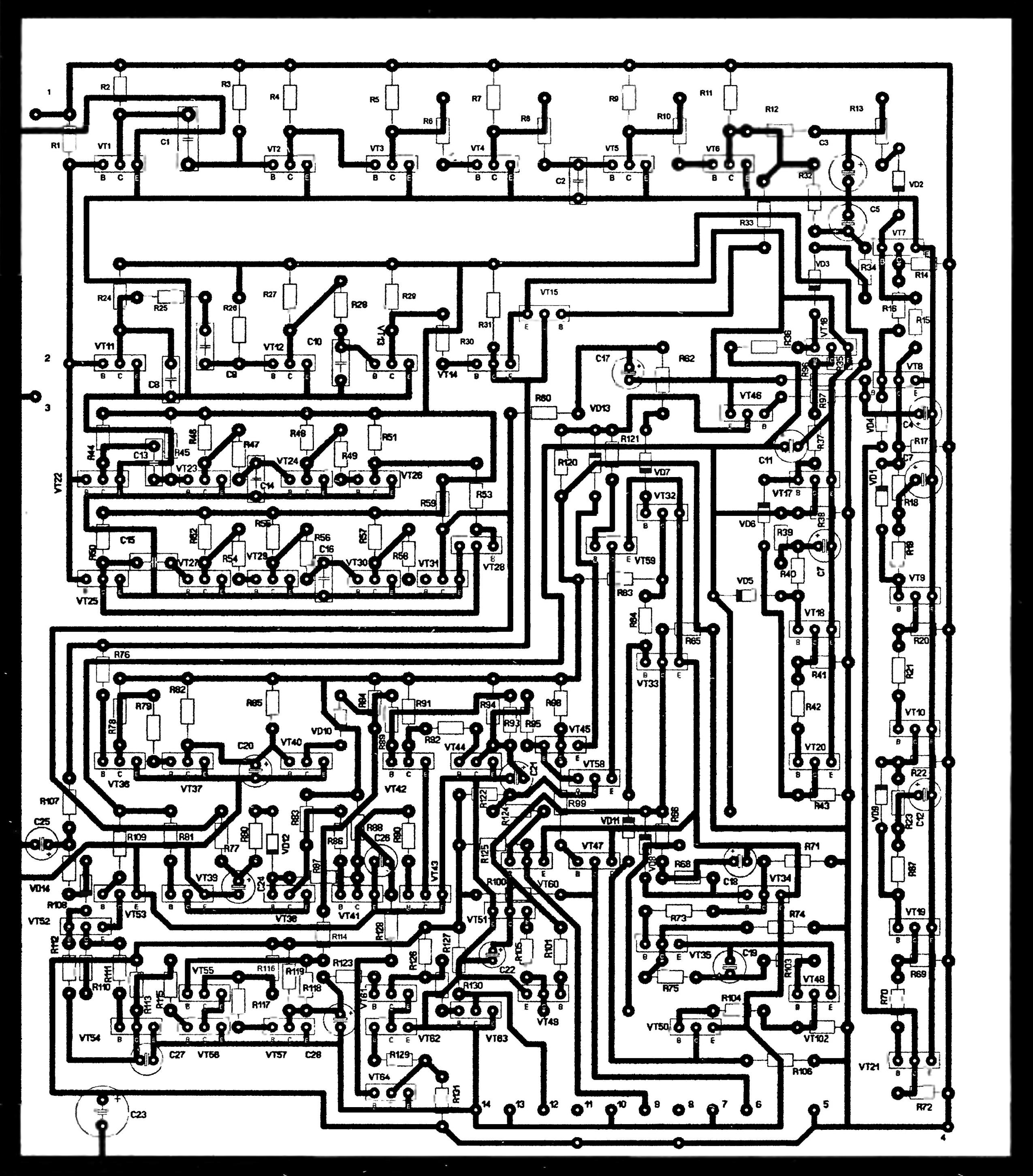
Fig. 2. A printed circuit Board of the control panel (refer base the collector and emitter of transistor Latin letters B, C and E respectively) (click to enlarge)
Control signals from the outputs 6, 9, 12 of the remote control are received at the inputs of switches. All switches on the same device, so it is enough to consider the work of one of them.
The switch (Fig. 3) allows you to enable or disable various devices when applied to its input control signal.
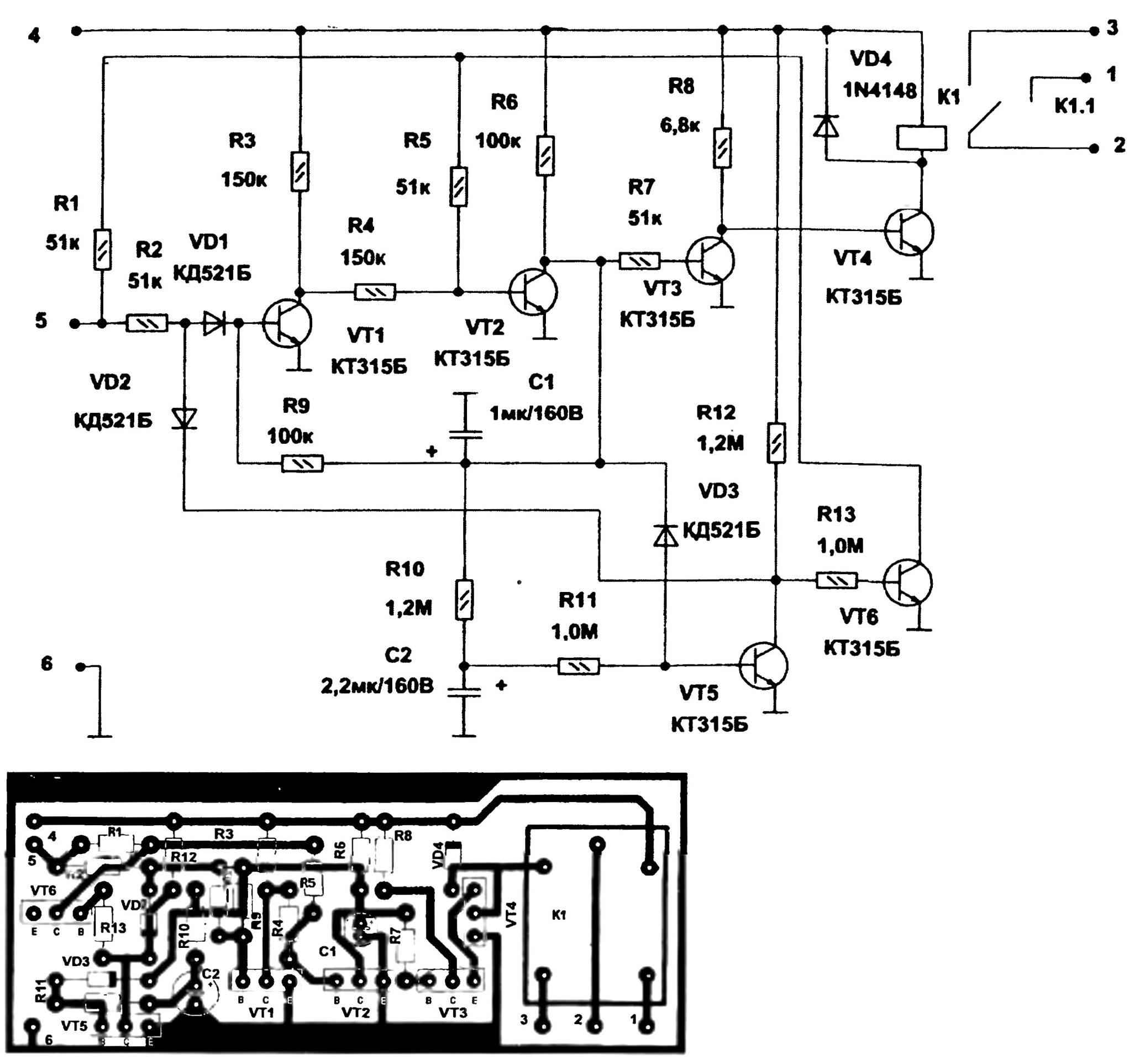
Fig. 3. Schematic and a printed circuit Board, switch (designation of the base, the collector and emitter of transistor Latin letters b, C, and E, respectively) (click to enlarge)
The device operates as follows. Supply voltage +12V is fed to input 4 from the control panel, to the first switch output 5 on the second switch - output 8, the third switch output 11. Sub-zero input 6 is connected to the first switch output 7 control output 10 the control - minus of the second switch 13 and the output - minus third switch. Input 5 receives the control signal (voltage high level), which passes through the resistor R1 and the resistor R2, the diode VD1 to the base transistor VT1, opening it, in this case, the transistor VT2 is closed. Generated at its collector voltage charges the capacitor C1, which through the resistor R9 maintains the open state of the transistor VT1, and transistor VT2 as a result, remains in the closed state.
Received the input 5 of the control signal, the transistors VT1 and VT2 remembered. Now high voltage from the collector of transistor VT2 will go through the resistor R7 to the base of transistor VT3, opening it, opens and the transistor VT4, which will include the relay K1. Will close the contacts and turn on the Executive unit. Simultaneously, the high voltage level with the collector of transistor VT2 will go through the resistor R10, the capacitor C2, a resistor R14 to the delay to the base of transistor VT5, opening it, and the transistor VT6 is closed. Another control signal received on the input 5, passes through resistor R2, diode VD2 to the open collector of the transistor VT5, and this signal passes through resistors R1 and R5 to the base of transistor VT2, opening it. Through the open transistor VT2 will discharge the capacitor C1. Closes the transistors VT3 and VT4. Will turn off the relay K1 and the Executive device.
When the control signal will trigger the relay K1 closes the terminals 3, 2 and turns on the actuator. Subsequent signal control via relay K1 will turn off the actuator, Etc.
In the device used relay K1 type FRS10С-03. Relay 12V: 3A/125V. Capacitors C1, C2 is electrolytic. Resistors - type MLT 0.125 watts. A printed circuit Board dimensions 75x30 mm is depicted in figure 3.