The versatility of the described device in that it can not only to turn on and off at a specified time four load, but also to turn obsolete machine AT the computer ATC and thus perform the function "protivoavariynogo" funds.
When there is a need to switch multiple loads for a given the program is convenient to use a digital watch with multiple alarms equipped with electronic keys. However, if you want to manage with computer, and the watch will no longer fit. The proposed timer allows manage up to four independent channels. For this there are 16 events each of which can change the state of any channel (enable or off) at the scheduled time and day of the week. You can control channels directly from the computer attached to the device with him the installation of the current time and the event setting in the timer.
The device allows a regular computer to implement AT the advanced power management is similar to machines of standard ATC (software off and be included in the appointed time), and to control the peripheral devices (printer, scanner, external modem). To use the timer in "protivoavariynogo" funds are needed program that automatically regularly resets the time off and then inclusion in a few minutes. If the computer freezes the timer, turning off on some time the food will produce a cold reset of the system.
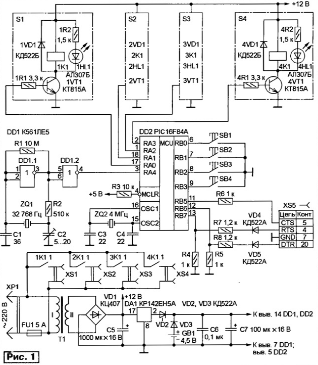
Schematic diagram of the device depicted in Fig. 1. It is based on PIC controller PIC16F84A-04 (DD2). Clock frequency (4 MHz) quartz sets the resonator ZQ2. On the element DD1.1 is a pulse generator with a frequency of follow 32768 Hz for timing. The pulse generator receives through the buffer element DD1.2 on the external input of the counter RTCC microcontroller. The desired frequency and, consequently, the precision of a watch set an inferior capacitor C2.

(click to enlarge)
Transistors 1VT1-4VT1 loaded relay 1TO1-4K1, the contacts of which are included in the chain supply power to the loads connected to the sockets XS1-XS4. LEDs 1HL1-4HL1 - status indicators loads.
The computer controls the device via RS-232. Since the microcontroller PIC16F84A has no built-in serial interface, the last implemented in software. Signals COM port used is not standard. On line DTR is the synchronization of the transmitted data line RTS PC transmits information, and the CTS line gets it out of the controller. Data transmitted in full duplex mode and supplemented by the control bytes to check the correctness of the information. More used to the interface described in the article the author of "Interface PIC controller with a PC" ("Radio", 2003, № 7, p. 20-22).
Chain R4R7VD4 and R5R8VD5 convert RS-232 levels to TTL levels for the inputs microcontroller. TTL level output from the microcontroller is sufficient for direct line control RS-232, which allowed to simplify the scheme approval.
After power-up the microcontroller DD2 is set to the initial state in which all channels are off, the clock is reset to zero, and control of loads locked, to prevent erroneous inclusion. Producing setting device, the computer transmits the current time, day of the week and the options for events. All information about it is stored in non-volatile EEPROM memory microcontroller. Each event contains the number of the load which it controls, information about manufactured action (on or off), time positives (including day of week) and can be in "off" condition (does not perform any operation) and in "daily" mode (occurs in the specified time, regardless of the day of the week).
After setting the time and channel settings the device can be used as offline (while disconnected communication cable from the connector XS5) and running computer. Since the RS-232 interface allows connecting and disconnecting cable when the devices (hot plug), it can be done at any time.
For direct control of channels using the buttons SB1-SB4. Hold any one of them pressed for more than 0.5 s leads to state change the corresponding channel.
The time delay is implemented in software and prevents switching loads in case of accidental taps. The port In the microcontroller is configured so that it input line RB0 - RB3 and RB5 are connected through internal resistors to the bus power.
The power supply of the timer is made according to the traditional scheme and has no peculiar features. The use of step-down transformer T1 due to the need galvanic isolation of the mains and the computer. Battery GB1 - backup power source hours during power outages.
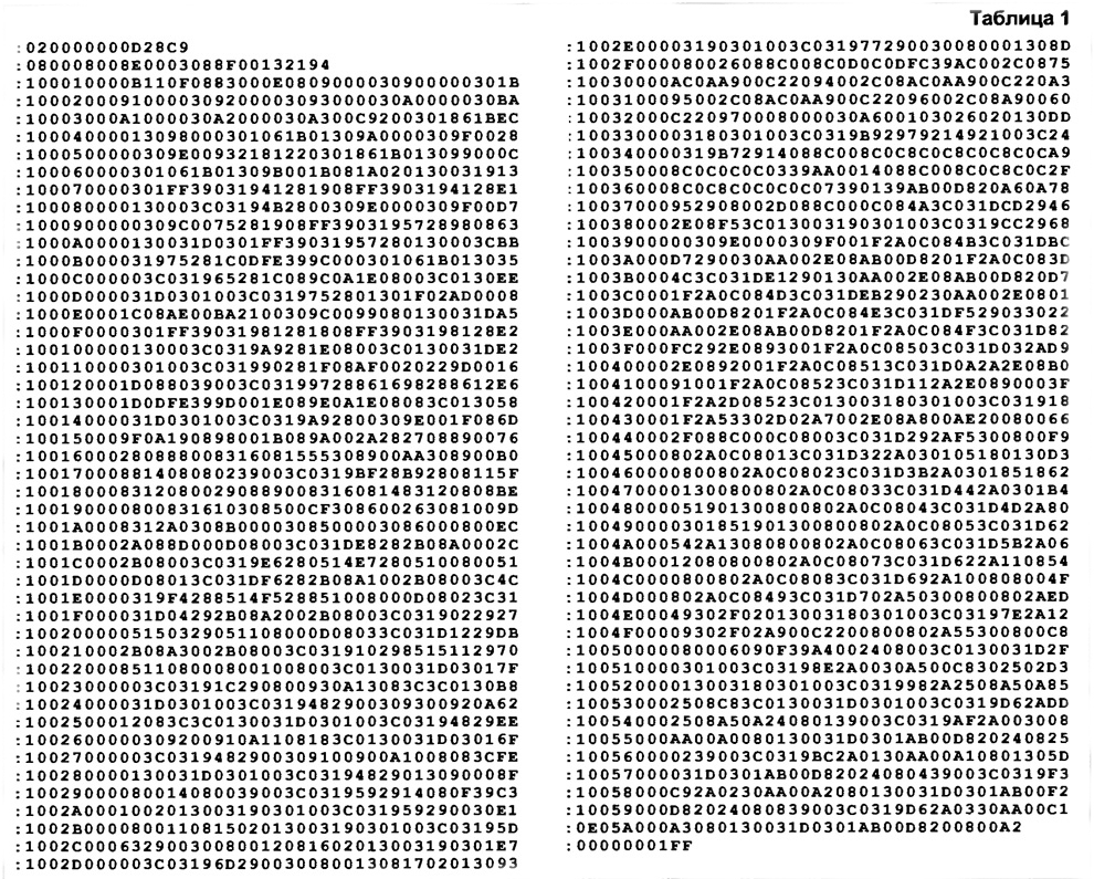
Codes firmware of the microcontroller are shown in table. 1. When programming you need to set bits in the configuration word: the type of oscillator (OSC) - HS, watchdog timer (WDT) is switched off, the delay after power-up (FWRTE) - resolved.

(click to enlarge)
The computer to communicate with the timer is via a dynamically loadable library timercom.dll.
Library and description of the software interface (API) for work with it and create your own wrapper to work with the device
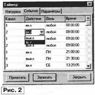
For the installation of events and manual control loads the program TIMER. In its main window (Fig. 2) there are three tabs. The first one ("Load") displays the status of the loads, which can be changed by removing or placement in meet the soup the first box in the second ("Events"), provides the terms 16 event the channel number of the load, the required action, the time and day of the week when it should to happen. In the "Settings" tab you can select the COM port that is connected device, and set the box that allows the program to get data from the device immediately after launch. After you change the settings of the event or condition loads you must click "Save" to transfer the new information timer (this automatically sets the current time). Button "Read" leads to the download of the current data unit.

The device is assembled on the PCB and arranged in the housing of the surge suppressor "Pilot". Buttons, LEDs and socket XS1 is installed on the side wall.
The transformer T1 is any compact with the secondary winding 12 V. as 1TO1-4K1 applied import relay TRU-12VDC-SB-CL with an operating voltage of 12 V and contacts 5 A (coil resistance is 400...500 Ohm). Backup source power GB1 - battery pack or cell voltage ...4,5 3,6 V. power from it current does not exceed 8 mA.
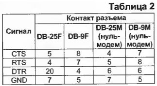
Connect the timer to the COM port of the computer as a modem, and null modem cable. The pin assignments for each case are given in table. 2.

Author: S. Kuleshov, Kurgan


