


")

The author offers an unconditional disconnect the TV from the network in night (from midnight to seven a.m.) developed and use apply them with a simple device. Except as described in the article reasons, it can serve to limit TV viewing by children.
Unfortunately, the quality of power supply in many parts of our country leaves to be desired: surges and voltage fluctuations in the network are often the cause failure of electronic equipment, especially imported most often constantly connected to the network. Obviously, most dangerously elevated (more 240 V) voltage, mostly occurring at night.
To a certain extent to solve this problem provided here will help the device - the timer stop time. Although the device used for limitations of the functioning of the TV, it is quite applicable to other equipment. Its main functions are: lowering of the voltage supplied to the TV, which is applied to the autotransformer, full forced off apparatus with the onset of midnight, and the inclusion of it in the morning.
This mode of operation is acceptable for most modern domestic and foreign models: slide 15…20 V power supply does not violate work switching power supplies, and setting apparatus (frequency channels and other settings are retained in memory for quite a long time even when power is off. Yet one advantage of this mode - turn on loop demagnetization in the TV that promptly removes color stains that occur on the screen of the tube due to the effects of external magnetic fields. Use for switching load lectromagnetic relays and timing for network frequency of 50 Hz has significantly simplified the device and get rid of sites that require a settings. Somewhat to his disadvantage, the need to external electronic watches.
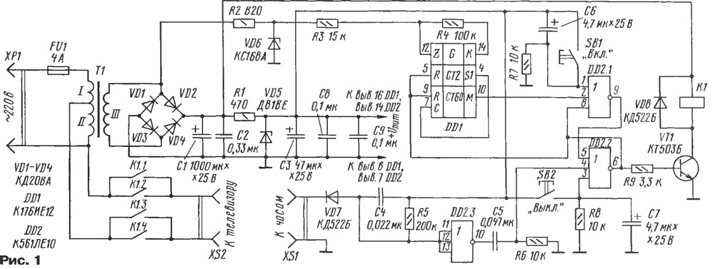
Schematic diagram of the timer is presented in Fig. 1. Switch on the TV manages the trigger on the elements DD2.1, DD2.2 through the cascade transistor VT1 and relay K1. In the original single state of the trigger output of the element DD2.2 there is level 1, the transistor VT1 is open, through the winding of relay K1 is leaking current and the TV is connected to the network. Counter chip DD1 is off level 1, arriving at its conclusions of 5 and 9 (the reset signal). In this state, the device is until midnight.
(click to enlarge)
At the specified time on the connector XS1 comes negative differential voltage hours. Appearing at the output of the element DD2.3 positive momentum through a chain C5R6 switches the trigger on the elements DD2.1, DD2.2 in zero the condition, when the output of the element DD2.2 there is a level 0. The transistor VT1, the relay is de-energized and TV.
At the same time starts the countdown counter DD1. Clock is for him the frequency of the mains voltage of 50 Hz. For this it is the positive half, remove transformer T1 is limited by the Zener diode VD6 and pass through the resistor R3 to the input (pin 12) DD1 chip.
Although the upper circuit portion of the counter divides the input frequency at 32768, and bottom - 60, after removing the reset signal from pin 9 level 1 at the output M (pin 10) of the divider will appear after the passage 39 of the counting pulses. Therefore, the holding time of the timer is equal to TB = 0,02 · 32768 · 39 = 25559 with, or 7 hours 5 minutes 59 seconds.
It is during this period, measured from midnight at pin 10 of the chip DD1 will be level 1, which will put the trigger in the original one. Relays work, you will have the TV connected to the network, and the counter is again blocked.
The device remains in standby until midnight. Real time the TV may differ from those designed for one or two minutes because frequency instability of the mains voltage.
SB1 and SB2 buttons allow you to control the TV manually. Elements R7, C6 form a chain initial setup when you connect the device to the network.
Most simply, the device can be connected to the clock, which is made on chips series C. In this case, the connector XS1 remove the signal from the output 3 chip KIE. While sub-zero circuitry and hours should merge.
If the watch is made on BIS CIC as described by S. A. Biryukov in the book "Electronic watch on MOS integrated circuits" (M.: Radio and communication, 1993), they need to embed the shaper signal "midnight". Principal the Assembly diagram shown in Fig. 2.
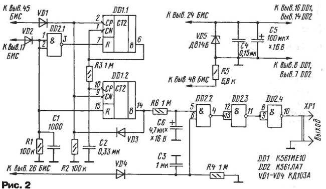
It is based on the recognition the state of the segments g indicator hours. Counter DD1.1 allocates the testimony hours in which the specified segment is lit in all places, and the counter DD1.2, on the contrary, are those indications in which the segment g everywhere suppressed. However, the resolution of the second counter is issued through the chain R3C2 only when triggered first. Therefore, the level 1 appears at pin 14 of the chip only when DD1 the transition time hours from 23:59 to 00:00, i.e. midnight. As a result at the output of the element D2.4 is formed of a negative pulse with a duration of 2 min.
The detector signals flashing dividing points in hours, assembled on the elements VD4, R4, C3, prohibits the operation of the generator in modes stopwatch and timer hours. In these modes, the indicator dots are off.
Chain R6C6 prevents false triggering of the device when switching modes, for example, when switching from the clock 22:38 to the indication of the alarm clock 07:00. Chain VD2R1C1 filters out the pulses of the frequency of filling the segment pulses, formed BIS.
It should again be noted feature of the device: it is forcibly turned off the load at midnight. This may be unacceptable if the TV is relatively often used after midnight. Lock mode can be set the switch in the trigger circuit in series with the diode VD7 (see Fig. 1). But the switch might have forgotten to include. More convenient electronic Assembly off the chain on one night. For its implementation need to change the input circuit of timer in accordance with Fig. 3.
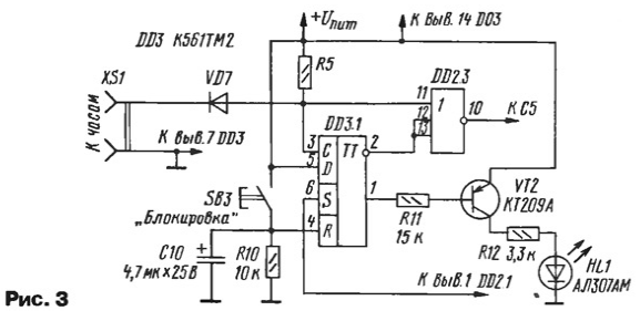
Designation of added elements continue the numbering main unit. When you press the button SB3 "Lock" more the trigger DD3.1 translates to the zero state, including the lock mode. In the result of the passage of the signal at the output of the element DD2.3 prohibited. Next then, the positive differential input pulse automatically returns the trigger DD3.1 in one state, removing the ban. Therefore, for one night switch off the TV will be blocked. Indicator HL1 indicates the start lockdown mode.
Rectifier bridge VD1 - VD4 device, you can use any diodes or assemblies that provide a direct current of 100 mA. Zener VD5 - on any voltage 8…10 V. the Remaining diodes - any low-power silicon. In the device used resistors MLT, capacitors K50-35, K50-40, C50-51 (oxide) and km, K10-7 (the rest). Chip CLA, CLE can be replaced with counterparts from series C, 564. Transistor VT1 can be from any series KT3102, CT. Relay - RES (passport RF4.500.131), the contact group connect in pairs parallel. Button, led and connector XS1 can be any better small-sized.
To power the device applied industrial transformer, the magnetic core SLH. The winding of I contains 86 turns of wire with a diameter of 0.63 mm; winding II - 1600 turns of wire diameter 0,224 mm; winding III - 105 turns of wire diameter 0,335 mm. At independent manufacture of the transformer need to ensure that the ratio of numbers of turns of the windings II and I in the range of 15 and 12… the voltage across winding III - 11…14V.
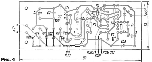
Most of the details of the timer is placed on the circuit Board, the drawing of which depicted in Fig. 4 (without the additional elements shown in Fig. 3).
When installation capacitors C8 and C9 are soldered to the power pins of the chip DD1 and DD2 respectively. The wires going to the buttons, must have a minimum length.
Author: Dmitry Nikishin, Kaluga