


")

The author tells about one of the common causes of failure household refrigerators and offers two devices for their protection.
In the instructions of some household refrigerators, for example, STINOL, it is said that their re-inclusion in the network is allowed no earlier than 4…5 minutes after shutdown. This time is required for condensation and pressure decay refrigerant. Otherwise, the starting load on the motor the compressor is too high, causing overheating of windings. In this the situation of engine failure is most likely.
To fulfill this requirement without the use of additional protection devices impossible. Appliances included around the clock. So take him out building, it is quite usual for our electricity, even short stoppage of supply of electricity, especially at night or when there are no hosts. In such cases must automatically delay the inclusion of the fridge approximately 5 min after restoration of voltage. This the function can perform the timer, the circuit of which is shown in Fig. 1.
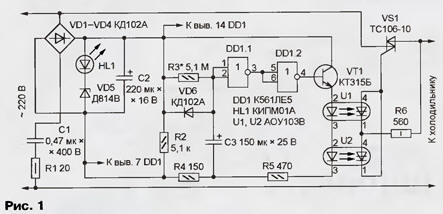
It works as follows. For the first time after the filing of the mains voltage the capacitor C3 is discharged and begins charging through the resistor R3. Logic element DD1.1 serves as a threshold device. Until the voltage at its inputs below the threshold switch, its output is high, and at the exit of the element DD1.2 - low logic level. Transistor VT1 is closed, the current in its amiterno chain no. Therefore, the thyristors optocouplers U1 and U2, and with them the triac VS1 closed. The power circuit of the refrigerator open.
Approximately 5 minutes the voltage on the capacitor C3 reaches a level at which will begin a change of state of the elements DD1.1, DD1.2 and opening transistor VT1. Due to positive feedback through resistors R4 and R5 this process develops in an avalanche, the current through the LEDs of the optocouplers U1, U2 increases abruptly. As a result, the photothyristors optocouplers alternately open in the beginning of each half cycle of the mains voltage, and flowing through them and resistor R6 current opens the triac VS1. The refrigerator is plugged in.
If the voltage disappears for more than 1…2, the capacitors C2 and C3 time to discharge (the latter through the diode VD6). Resistor R2 serves to accelerate the process of discharge. With the advent of voltage application described above again and the fridge will be included only after 5 min.
The feeding unit of the timer is assembled by the transformerless circuit with damping capacitor C1. Resistor R1 limits the inrush current at power up. The rectified diode bridge VD1 - VD4 stable voltage by using series-connected the HL1 led and Zener diode VD5. The led glow is a sign the presence of voltage in the network.
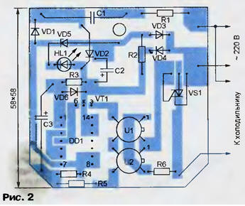
The timer is assembled in the housing from the power supply BP-3 (so-called network adapter), which is staffed with some calculators. Socket for the fridge is fixed on the casing unit on the side opposite the plug and inside the enclosure - PCB from foil fiberglass, shown in Fig. 2.
Chip CLI without any correction scheme can be replaced by CLA. Transistor VT1 - series CT, KT315 with any alphabetic indices. As VD1-VD4 suitable suitable in size, low-power diodes with a valid the rectified current of at least 30 mA, and the replacement VD6 should choose low reverse current, for example, KD102B KDA. HL1 led - any color of the glow with a maximum current of 30 mA. Forward voltage drop on the LEDs type may vary 1 …2, what to consider when choosing the Zener diode VD5. The total voltage across the Zener diode and the led should not to go beyond 10…15 V.
Capacitor C1 - K73-17, C2 - any oxide, C3 - oxide with a small current leakage, for example, K52 series. All resistors - MLT or C2-33 defined in the diagram power. Triac VS1 (its voltage class shall be not less than 4) supply aluminum heat sink with an area of several square centimeters and attached to the Board, for example, epoxy glue.
The establishment timer is to install the required delay selection of resistor R3. Note that an excessive increase the resistance of the resistor leads to the variability of delays caused the influence of the leakage currents of the capacitor C3 between conductors and printed circuit boards. Current leakage of the oxide of the capacitor for a long period of time, which were not under the voltage is usually increased. So be sure to check latency after how the timer will work continuously for at least a day, and if necessary, get it again.
Similar in purpose and principle of operation the timer can be collected according to the scheme it is shown in Fig. 3.
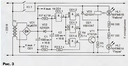
Its main difference is that the load (fridge) commute is not a triac, and with the help of relay K1. Trigger, switching at reaching the voltage on the capacitor C2 threshold level, in this form if the elements DD1.1 and DD1.4. The parallel connected elements DD1.2, DD1.3 - buffer amp, managing electronic key on the transistor VT1, the collector circuit of which includes the winding of relay K1. The resistor R5 is needed to accelerate discharge the capacitors after turning off the mains voltage. Of current flowing through it insufficient to hold the relay K1 is triggered in condition. The transformer T1, a diode bridge VD1 and the capacitor C1 of the power node timer.
LEDs HL1 and HL2 are used to indicate the presence of voltage and condition timer. If none of them is not on, the line voltage is absent. Since the appearance of voltage and before turning on the refrigerator lit led HL1. Then he goes out and lights up the led HL2.
Picking up the relay, note that the contacts must be rated for switching current of several amperes consumed by the refrigerator in the launcher mode. In the author's version of the timer is applied the relay REN-18, passport RH.564.706. The transformer T1 with the voltage on the secondary winding 6 In load current 300 mA. The rectified voltage across capacitor C1 was 7…8 V. If you have relay with a large voltage, the voltage on the secondary winding the transformer should be increased accordingly. However, if you increase the rectified voltage In excess of 15 DD1 chip should feed through the simplest regulator with an output voltage of no more than specified. Output stabilizer definitely sachunterricht 1 kOhm resistor that generates the discharge circuit of the capacitor C2.
The timer is assembled on the Board of one-sided foil fiberglass. Installation almost all circuits formed by a printing method, and printed conductors located near one of the edges of the boards with a width of 80 mm (Fig. 4). With the rest of her the surface of the foil is removed, there is established the relay K1 and the transformer T1.
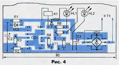
Cost close the lid of insulating material with holes for the LEDs and the outlet for the fridge. The establishment timer is to install required excerpts by selection of the resistance of the resistor R1.
Author: I. Nechaev, Kursk