


")

In our daily life there are procedures to perform that it is easy, but their monotony is causing inconvenience. They can include cyclically repeatable day-day flow of signals in exactly the specified time (for example, delivery of calls to schools). Such processes themselves "asked" to automate them. The author of this design not only solved this task, but also has provided a variety of options for its execution.
The proposed device allows, in accordance with any one of 16 pre programmed schedule options to turn the beep on 6…8 C in the interval of time from 4 h 00 min to 19 h 55 min
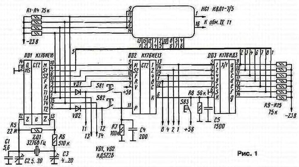
The alarm device consists of an electronic clock, external source power. Electronic clock (Fig. 1) is assembled on the well-known chips CIE (DD1), CIE (DD2). CIJ (DD3). Them on and model the operation is considered in detail in [1, 2]. Current time displays indicator HG1 (IVL-7/5).
(click to enlarge)
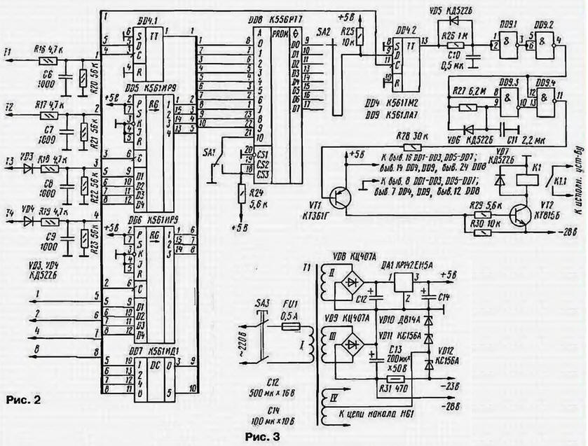
Schematic diagram of the programmer shown in Fig. 2. Chip DD4.1, DD5. DD6 form the register, the outputs of which formed an eight-bit code current time. For informational inputs of these chips in the code 1-2-4-8 served the signals of the current time from the outputs of the chip DD2 electronic clock. At the moment the appearance of signals of tens of hours With the input element DD4.1 with a slight delay the leading edge signal T4 from the output (pin. 15) DD1 chip. In the result of the output element DD4.1 code set up to tens of hours.
Similarly, the rising edge of signal TK, T2 coming from the outputs chip DD1 to the inputs of circuits DD5, DD6, the outputs are adjusted codes of units of hours and tens of minutes, respectively. For example, when the current time 08 hours and 30 minutes on the outputs of the register set code 00001110. which is not changes within 10 minutes. Thus, dynamic information about the current time generated by the circuits DD1, DD2 to display on the indicator HG1, r register on chips DD4.1. DD5 and DD6 is converted to static
At the moment of arrival to the input of the programmer signal T1 at the output of the decoder DD7 code set up to units of minutes. If the number of units of minutes equal to 0 or 5 on conclusions 3 and 6 of chip DD7 respectively formed signal log. 1. For example, if the current time is 08: 30 on the address inputs A0 - A9 EPROM for DD8 the leading edge of the signal T1 is set desethylatrazine code 0000111010. When the coincidence desaturating code current time and programmed code time of the signal on the output DD8 will appear in the alarm log. 1.
An event is remembered by the trigger DD4.2 on the rising edge of the signal T1, which comes to its input (pin. 11) with a slight delay. The signal log. 1 the output of this chip will be maintained for 1 min. On his front the front of the circuit elements DD9.3, DD9.4 with a slight delay form a on your the output signal of the log. 0 with a duration of at least 6 p. This signal is input to amplifier, the transistors VT1, VT2 are opened, the relay K1 is activated and its the contacts K1.1 to 6 with a short circuit power the audible alarm. Elements R26 and C10 creating a delay of the leading edge of the output signal of the trigger DD4.2 at the time not less than 0.32 C.
The power supply warning device (Fig. 3) provides a stable voltage +5 and -23 V. stabilized -28 V and AC voltage of the filament indicator 5 V. source +5 V alarm device consumes about 130 mA. source -28 B (when relay K1) - 90 mA. The heating circuit of the indicator HG1 consumes a current of 120 mA.
(click to enlarge)
All elements of the signaling device placed on the same Board. During installation used oxide capacitors K50-16 (C12 - C14), trimmers CT-21 (S2, C3). Km-6 (the rest). All resistors - MLT. Button SB1 - SB3 and switches SA1, SA2 - any small. Mains transformer 10W - any, providing indicated in Fig. 3 voltage. Relay K1 - RP working on voltage 24 V.
Chip DD8 installed on a separate block. Programmed it using programmer that can perform the same as published in [3].
Before programming, you need to create a table, first column (which record the time for the alarm (timetable), in the second, third, the fourth and fifth to the corresponding binary desethylatrazine code this time in the sixth position of the switch SA1 (log. 0. log. 1). at which the device will work with the selected schedule, and the seventh - selected for programming the EPROM output. Earlier in the text and shown here in the table given examples of the transition time of the signal in desethylatrazine binary code.
Because each of the eight positions of the switch SA2 is connected to two of the position of the switch SA1, the total number of options timesheet submission calls - implemented data of EEPROM is 16.
After programming the chip DD8 set in the alarm device and check the correctness of its programming. For this purpose, the switches SA1 and SA2 transferred to the desired position and press SB3 - correction, SB1 - installation minutes SB2 - setting the clock set the indicator HG1 time 00 h 00 min Then press SB1 again "chased" this is the time to 00 h 00 min If you run enough loud will operate relay K1. His response should be compared with the feed table is ringing.
In schools schedule of submission calls on weekdays and Saturdays. as a rule, not are the same, so for ease of reference signal by a device, such schedules are entered into EPROM on one output if different from the address inputs A10. Then schedule calls will be easy to choose the switch SA1.
Literature
Author: N. Klemenov, Smolensk