The principle of operation of this timer is based on the fact that the charging time of a fully a discharged capacitor is determined by the product of capacitance of this capacitor the resistance circuit of a charge. Setting the value of this work by selecting capacitance and resistance, it is possible to obtain the required charging time.
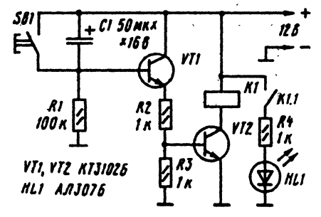
Schematic diagram of the time switch shown in the figure.

This time relay can be collected with his own hands unnecessarily in the scheme there is scarce details. When connecting to the power supply circuit starts charging of the capacitor C1 through resistors R2 and R3 and the emitter junction of transistor VT1. it opens and the resistor R3 forms a voltage drop from flow through it emitter current. This voltage drop is unlocked transistor VT2, and actuates solenoid relay K1, through his contacts K1.1 connects to the bus power led HL1. Resistor R4 limits the current to the led.
As the charge voltage on the capacitor increases while the charge current reduced. Accordingly, decreases the emitter current and the voltage drop across the resistor R3. Finally, when a certain voltage on the capacitor charging current becomes so small. the transistor VT1 is locked, it is locked transistor VT2. As a result the relay is released and the led goes out. For the next start time relay must briefly press the SB1 to to completely discharge the capacitor C1.
The desired length of time during which the relay K1 is the triggered condition is established by selection of the capacitance of the capacitor and resistors R2 and R3. If the relay has another pair of contacts, can be used to enable other consumers or turning them off. But then the second pair of contacts must be normally closed.
The choice of type relay produced by the amount of its operating voltage which must be equal to the supply voltage of the device. In the diagram, the relay is designed for the supply voltage is 12 V.


