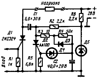
Device, scheme of which is shown in the figure, provides the load loss through a well-defined period of time after switching it on.

The device is produced by the pulse applied to the PA input. In the initial state when the input signal of the thyristor D1 is closed and, consequently, the current load does not leak. The capacitor C2 through resistors R3 - R4 is charged up to the breakdown voltage of the Zener diode D4. This opens the thyristor D3 and bypasses the control circuit. The capacitor C1 is charged up to the voltage of the power source. In this state, the device can be arbitrarily long.
Upon receipt of the input pulse thyristor D1 is opened, connecting the load to the power source. Capacitor C1 is recharged via an open thyristor D1, the thyristor D2 at the time of discharge of the capacitor C1 turns off. After closing the thyristor D2 again begins to charge capacitor C1. As soon as the voltage across it exceeds the breakdown voltage of the Zener diode D4, opens the thyristor D3 and the capacitor C1 discharges through it. The thyristor D1 is turned off and the device returns to its original state.
Thus, the time during which included load, is determined by the charging time of the capacitor C2 until the breakdown voltage of the Zener diode D4.
Diode D3 provides a fast discharge of the capacitor C2 when the lid of the thyristor D2. The Zener diode D5 stabilizes the voltage of timing chain.
When using the items specified on the schematic diagram, the device provides an exposure of around 1 s.
In time relay, you can use any low-voltage thyristors, two series-connected Zener D (D5) and a Zener diode XA (D4).
In the process, the polarity of the voltage on the capacitor C1 is changed, then the latter should use the paper capacitor.
Literature
Publication: N. Bolshakov, rf.atnn.ru


