


")

In small organizations, and firms would like to use a secondary clock with stepper motors 24 V, but it takes "time station",
underpinning their work. Buy this plant are not affordable for everyone the company, besides its maintenance cost. In the solution this problem can help Amateurs-designers. They are quite capable to build a simple "watch station", designed for a small number of secondary hours. One embodiment of such stations has already been described by S. Alekseev (see "Radio", 1985, No. 10, pp. 44,45). In the article published below for the attention of readers the description of yet another primary quartz watches, which otherwise solved the problem of changing the polarity of the incoming secondary clock pulse voltage 24 V.
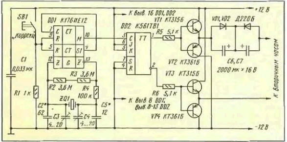
The station is designed to connect five hours secondary. Its schematic diagram shown in the figure. Generator minute pulses is made on the chip and DD1 quartz resonator ZQ1 frequency of 32 768 Hz included in the model scheme [1]. With the exit of DD1 chip (vyv. 10) the one-minute pulses are received at the counting input trigger DD2. The trigger changes its state every time the input, you receive the positive voltage drop. Direct and inverse outputs of the trigger connected to the bases of transistors VT1, VT2 and VTЗ, VT4 included on the pavement scheme. The bridge changes the polarity of the voltage applied to the secondary engines hours, depending on the condition of the trigger. For a single state of the trigger opened the transistors VT1, VТ4 and through the chain of C6, C7[2]. windings of electric motors secondary flows hours a current pulse.
If you change the state of the trigger opens the transistors VТ2. VТЗ and polarity connect the power source to the load also changes. Diodes VD1, VD2 eliminate the possibility of reversal of the capacitors C6, C7. The capacitance of the capacitors choose depending on the number of connected secondary hours achieving reliable control of their swing. The diagram shows the capacity for the case connect five hours.
As the power source is rechargeable out of ten elements D-0,55. used to carry a radio. Any other battery voltage of 12 V.
During operation the battery must be charged by a current of about 10 mA. From for reasons of safety of operation in the battery charger should be used low power mains transformer.
The impact of network interference can be significantly reduced by creating a screen winding and providing reliable grounding. Additional interference mitigation is done using the throttle, breaks included in the plus and negative wires connecting the rectifier and battery. Windings can be wound at the same time two mounting wires on the ferrite ring MNM. Sizes the ring should be such that it is located 10… 15 turns. Output rectifier and the rechargeable battery shall be shorted capacitors with a capacity of 0.033 microfarads and more with low parasitic inductance. In particular, they should not be paper. More information can be found in [3].
The average value of the discharge current and charging the battery is evaluated by experienced installation of power balance between them. To do this, in the first months operating watch station you need to watch the voltage the rechargeable batteries. It must be equal to V. 13 which corresponds to 60% capacity to be charged. Upon detection of a noticeable trend towards a decrease or increase the battery voltage should increase or decrease its charging current selection the ballast resistor.
When you connect your watch to the network with the notoriously unstable voltage instead the ballast resistor is recommended to install the current stabilizer. His perform in the circuit shown in Fig. 7,and article S. Semushin "current Sources and their the use of" (see "Radio". 1978. No. 2, p. 44). The entrance should set the voltage 26 V. In this case to set the Zener current V1 8 mA may will need to find the resistance of the resistor R8. The resistors R1-R6 is more convenient replace the variable resistor. Instead of transistors GTG and suitable GTV accordingly CTV and CTV.
The application of this stabilizer ensures permanence of the established balance charging-discharging of the battery.
At steady-state voltage of the battery 13 In the existence of hours can "forget", not forgetting, however, to promptly transfer them to the summer and winter time.
Literature
Author: L. Maslyaev, St. Petersburg