Not long ago, the electronic watches were built on the so-called time chip series C and specialized chips series C (CIC) and CR (CRUI). Their main drawback is the limited capacity of improvement (any change required hardware improvements). Favorably watches, collected on the basis of microcontroller. The scheme is greatly simplified, and the "upgrade" can be performed without any hardware changes. Even the setting of the stroke hours can be purely software. Such watches are described in published below article.
Offer alarm clock with four-digit led indicator made on the basis of the microcontroller (MC) and show the time in 24-hour format with cancellation trailing zero in the tens digit of hours. Provided mode display minutes and seconds, the supply of short (duration of 1 second) sound at the beginning of each hour (if necessary, this feature can be turned off-i cation), two off the alarm and software configuration of the correction factor time, which affects the accuracy. The value of the coefficient and setting alarms stored in nonvolatile memory (EEPROM) MK. The status of alarms and signal "Every hour" is indicated by LEDs.
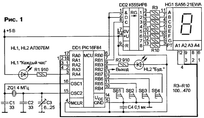
Schematic diagram of the device depicted in Fig. 1. It is based on the PIC16F84 microcontroller (DD1), the operating frequency which is set by the generator with external resonator ZQ1 at 4 MHz. The reset input of the MC (MCLR pin) directly connected to power bus and +5 V.

Five digit port A, all lines which are configured to output controls led HL1 and switches the level of the indicator HG1. Four senior level port B (RB4-RB7) are configured to input and accept control signals from buttons SB1 - SB4, which are connected to the pins without pull-up" resistors, because what's available in the MC. Bits RB0 and RB1 port is used to load in register DD2 semielemental code corresponding to the displayed figure. Discharge RB2 - signal output 3H or alarm (depending on version program), which can be connected directly to the system (ZP-1, RFP-3 and the like), to the input of the amplifier 3H or to the Executive device, for example, a relay that at the time the alarm will include radio, TV or other device.
LEDs HL1 and HL2 respectively indicate the state of the signal "Every hour" and alarms: HL1 lit when the signal is "Every hour" is enabled, a HL2 - if include at least one of the alarm or if you have enabled both.
The device incorporates a specialized time led indicator of the firm Kingbright containing four semielemental discharge with a common anode and two points indication of seconds between the mean ranks. As the findings of items a-g are common to all discharges which management indicator is possible only in the dynamic mode. For this design the indicator fits perfectly: the number of lines of input/output General purpose MK P1C16F84 does not allow implement a static display and dynamic with another indicator would have to combine the findings of the same elements of different discharges on the Board.
Resistors R3-R10 limit the current through the LEDs. The shift register DD2 introduced to conserve conclusions MK - it converts sequential code into parallel to the dynamic display.
Capacitor C4 filters the ripple in the power supply circuit MC. A place for him on the Board provided, it is soldered directly to the terminals of the socket MK side printed conductors.
Management program for MK written on standard MPASM assembler firms Microchip and compiled in the environment of MPLAB the same firm. Of the 1024 memory cells programs used MK about eight hundred, so that resources for improvement there are.
Immediately after power up, initializes the control program: the discharge ports are configured to input and output, a set timer 0, of the non-volatile memory is read to set alarms and the correction factor is time.
The main objective of the program is the formation of precise time intervals duration 1s - is solved by means of interrupts from timer 0. His predalien is connected to a quartz oscillator of the MCU and sets the division ratio of 16. In the case of timer 0 in each treatment interruption is recorded a number from 00h to OFh (this is the correction factor time in the source text he called TIME_SET), so the timer overflows not 256, and to example, for 250 cycles clock frequency (TIME_SET=5).
In this case, when using a crystal frequency of 4 MHz timer interrupt 0 occurs with a frequency of 1,000,000 Hz/250/16 = 250 Hz. After initialization, the program enters a loop, waiting for the interrupts and counts them. When the number of interrupts will be equal to 250, the current time increases for a second.
Interrupts from timer 0 and provide a dynamic indication. During their processing MCU sets the zero level of the pins RA0 - RA3 and thereby extinguishes indicator. Next to the register DD2 conclusions through MK RB0 and RB1 is loaded semielemental code corresponding to the character you want to display. Then on one of the findings of RAO-RA3 is set to high logic level due to what ignited one of familiarity. All this occurs 250 times per second, and through persistence of vision, the user sees immediately included all discharges.
The MSB is loaded into the register DD2 code is used to control points indicator, which flashes at a frequency of 1 Hz. Thus, with the help interrupt from timer 0 are solved two problems at once. In addition, in the subroutine interrupt processing MCU checks whether the displayed number is insignificant the zero in the left category, and if so, is semielemental code numbers On MK loads into register binary number 11111111 (led with a common anode, so one corresponds to a suppressed segment).
The keyboard is polled about 10 times per second, but after the first time some of the buttons and their combinations, the program does not respond to pressing in for 1 sec (for example, if button is held). This is for convenience manage the clock.

When the alarm on pin RB2 for 1 min intermittent signal appears 3H or, depending on the version of the program, high level (more precisely, pulses a repetition rate of 1 Hz). Flashing LEDs HL1 and HL2. After a minute call a special routine that restores the correct glow LEDs.
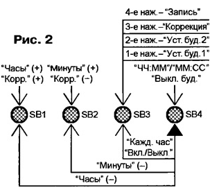
Device control buttons SB1-SB4, each of which combines several functions (see the mnemonic shown in Fig. 2). The clock operates in three modes: (display the current time), with a correction factor of time and mode setting alarms.
In native mode indicator HG1 displays the hours and minutes, the seconds the dots are blinking with a frequency of 1 Hz. Current time set buttons SB1 (hours) and SB2 (minutes): each click increases the indications on the unit, but if it is pressed SB4, decreases. Upon reaching a zero value bits minutes transfer to the category of hours is not happening.
If you hold the button SB4 within three seconds, the indicator instead of hours and minutes displays minutes and seconds of the current time.
The signal "Every hour" switch on and off button SB3 held at SB4 (HL1 led respectively lights up or goes out).
To switch to the setting mode alarm clocks click on the SB3. The indicator show a reading of the first clock, the second point light permanently. Hours and minutes to set the same buttons SB1 and SB2 (in this case only the readings increase). Pressing the button SB4 turns off the alarm clock, and the indicator remains only dashes when the elements of G). Subsequent the alarm is activated using the same button appear on the display, and registers alarm writes zeros (instead of the previous value). If you again click on button SB3, the display will show the readings of the second alarm, however second point goes out. Both alarms are configured identically.
The third button SB3 translates the clock mode of operation by a factor of time correction: the indicator displays symbols "X", where IT means EEPROM, and X is the current value of the coefficient in hexadecimal form; used the point still blinking. Button SB1 can be increased and the button SB2 - to reduce the value of the coefficient in the interval from Oh to Fh. Set number will be written to the timer 0 in the subroutine interrupt processing on it overflow.
When the fourth button SB3 setting alarms and value the coefficient is written to EEPROM: the first alarm clock - to addresses 02h-05h (respectively, minutes, tens of minutes, hours and tens of hours), the second addresses 06h-09h (in the same order), the coefficient at address 01 h.
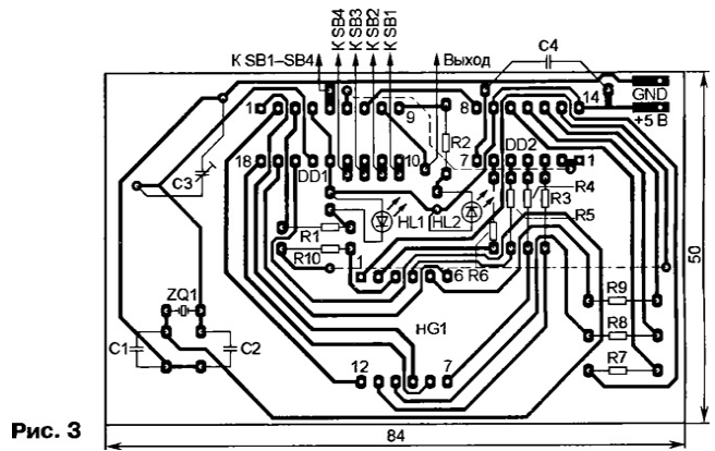
The device is mounted on a printed circuit Board manufactured according to the drawing shown in Fig. 3 (dashed lines represent wire jumper connecting printed conductors on the opposite side of the Board).

Without any changes in the scheme and programme MK can be applied PIC16C84 - one-time programmable analogue PIC16F84. Specified in the scheme to replace the indicator any other with four-digit common anode (preferably to conclusions same elements of the discharges were connected inside the indicator). Valid the use of four one-bit indicator, in this case as second point, you can apply two separate LEDs, cathodes connected to the right (the scheme), the output resistor R10 (if necessary using the key on the transistor). Resistors, capacitors, LEDs, buttons - any small-sized.
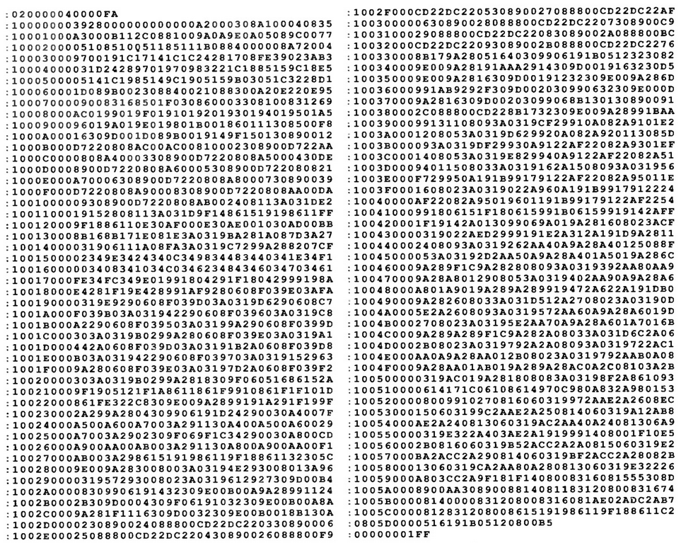
For hours designed three versions of the control program. Version 1.10 - basic (the HEX file given in the table). When the alarm-clock on pin RB2 a signal (square wave) at a frequency of 1 Hz. It can be used to control various actuators and signal generators 3H: from the simplest two or three logic elements to complex systems digital sound synthesis [1, 2]. Dynamic display in this version works constantly.

(click to enlarge)
In version 1.11 readout also runs continuously, but when triggered alarms and at the moment of generation of the signal "Every hour" on pin RB2 appear the packs of pulses with a repetition rate of 1 Hz (the frequency, filling bundles, corresponds to the frequency of interrupts from timer 0 - 250 Hz). This signal can be fed directly to the radiator or to the input of the amplifier 3H.
Version 1.20 is different from 1.11 only because the default dynamic indication it is off (all other functions work in ordinary hours mode). She starts to work, if you click on the SB4, and automatically turns off after 10 seconds When buttons are pressed and the alarm countdown this interval begins again. If the alarm is triggered off indication, it is not included: double-click SB4 to turn off the alarm and turn indication. This program is useful if to supply hours used battery is composed of battery cells or battery: switch off the display saves battery power.
When programming the MC in the configuration word to indicate the type of oscillator - XT, Power-up timer enabled, watchdog timer and code protection is turned off. Except in the cell 01 h non-volatile memory data is necessary to enter a number from Oh to Fh (correction factor time), and to addresses 02h-09h - install alarms.
If a software setting accuracy of the hours will be rough (which is quite likely), you should install is depicted in the diagram by dashed lines trimmer capacitor C3 (on PCB place provided for him).
The HEX files program versions 1.11 and 1.20, and the source all versions
Literature
Author: A. Vakulenko, Tyumen


