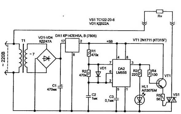
Sometimes it is necessary to periodically include a powerful network load, for example, advertising light, Christmas garland, sounder, etc. In this case you can use the diagram, Fig. 5.56.

Fig. 5.56. The control circuit turning on network load
The power of the device is stabilized voltage from the step-down voltage transformer. On the timer collected oscillator when the transistor VT1 controls the switching on of the triac VS1. Status of the chip can be judged by the LEDs HL1.
Author: Shelestov I. P.


