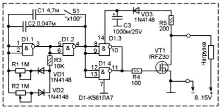
This device is connected in series to the load, constant eating voltage 8...15 V, and interrupts the current through the load.
The load current can be from units of milliamps to tens of amps. At this, the current consumption is negligible. The nature of the interrupt, i.e., the interrupt frequency, duty cycle, is regulated within very wide limits by means of two variables resistors, one of which is regulated by the time enabled state of the load, and the other time off. The difference can be up to 100 times.

The adjustment is made in two ranges, in the first period can be adjusted from 10 seconds to 0.1 seconds. In the second from 0.1 seconds to 0.001 seconds. That is in frequency terms, the 0.1 - 10 Hz 10 Hz-1 kHz.
It is desirable that the adjusting variable resistors were slotted type with linear adjustment of the resistance (as in the graphic equalizers audio). It is convenient, as well visually perceived difference in the time setting on and off state of the load, and when the need for frequency control (i.e. both parameters at once) handles resistors can be moved simultaneously.
With such a wide ranges of adjustment of the device can be used for a variety of assignments. For example, for the periodic supply of light signals, it is possible in a wide range to adjust the length of the lighted and off state of a headlight, or to adjust the brightness of a spotlight the rotation speed of the motor, by performing adjustment according to the principle pulse-width modulation.
Optionally, you can add other ranges, switching capacitors timing circuit of the multivibrator. Schematic diagram of the interrupter shown in figure. The basis of the scheme is a multivibrator logic elements chip CLA. Frequency control circuit of the multivibrator consists of capacitors C1, C2 and R-component, consisting of variable resistors R1, R2 constant of the resistor R3 and the switching diodes VD1 and VD2. Diodes VD1 and VD2 switch the resistors R1 and R2 depending on the phase of the generated pulse. In dependence of the set resistance of the corresponding resistor changes and the time corresponding to this phase resistor. Resistor R3 limits the minimum value of the time interval and eliminates the overload logic element because of its output circuit and input with minimum position the corresponding variable resistor.
The remaining two elements serve as a buffer between the multivibrator and the output cascade on VT1. The output is made to switch the field-effect transistor IRFZ30. It the difference is that the high current and very low resistance of the fully open channel. The current can reach. 30 a, While the channel resistance is a fraction of an Ohm. As a result the dissipated power on it even if the current close to the maximum is very small. Therefore it is enough small, we can say, symbolic of the plate radiator.
The breaker has only two output - "+" and " - " that it connects to the gap in the supply of the load. However, the power at the circuit of the multivibrator is fed from power source to the load, through the load. In operation, this voltage galloping, as the key VT1 almost closes power the chip D1. Sudden surge of power the chip didn't happen there is a scheme of the storage capacitor C3 is relatively large capacity and diode VD3 during the interval when the load is turned off charging the capacitor C3 through the diode VD3. At moments in time when the load included diode VD3 is closed, since its anode is negative potential, and the chip is fed by the charge accumulated by the capacitor C3 and diode VD3 eliminates the discharge of this capacitor through an open channel VT1.
Chip CLA can be replaced by CL or imported counterparts CD4001, CD4011 Generally, you can use any chip series C, CD, which there are at least three inverter logic element. That is, it is possible CLA, CLE, KPN and others. To include according to the Pinout. Extra elements such as the four elements of the chip you can connect K561LN2 parallel to each other (in place of D1.3, D1.4). It's even better as it increases power output is the key.
The 1N4148 diodes can be replaced by KD522, KD521, CD, CD.
The capacitor C1 may be of any type. The C2 condenser type K73-17 or similar (non-polar) C3 - analog K50-16. Resistors of any type. Variable resistors can also be of any type, but preferably slotted with a linear dependence adjustment of the resistance.
Before you start, it is desirable to allow the capacitor C3 to be charged, setting adjusting the resistors to the maximum position.
Author: R. Lyzhin


