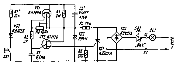
To not unnecessarily burned bright light lamps in the entrance of the house, in the hallway of the office, in the corridor of multi-bedroom, enough to complement the wall power switch automatic-economy that will continue to provide a minimum illuminance, and only after pressing the trigger button for a few minutes to turn on the light bulb at full power. This machine will allow to reduce energy consumption by at least double.
Where there is no switch, for example in an ordinary apartment building, it can be easily installed on the ground floor and in stairwells other floors to have duplicate buttons are connected in parallel to the main one.

Machine-economy (Fig.1), which is a trinistorny power control with pulse-phase control, include in the grid consistently with lighting incandescent lamp (EL1). When the closed contacts of the switch SB2 AC line voltage is rectified by a diode bridge VD3. With its pulsating output voltage is supplied to SCR VS1 and a voltage regulator R5VD2 - unijunction transistor VT2.
With the beginning of each halfwave of the mains voltage will charge capacitor C1 through resistors R3, R2 and field-effect transistor VT1. In the moments when the capacitor is charged up to the voltage of opening unijunction transistor, it is quickly discharged through an open transition of the transistor and the circuit control electrode of SCR. This leads to the opening of trinis Torah and the supply of voltage to the lamp EL1. The smaller the charging current of the capacitor C1, the later open SCR and the dimmer lamp is lit.
In the initial state, which is the standby mode of the device, the capacitor C2 is discharged, therefore, the transistor VT1 is closed. At this time, the charging current of the capacitor C1 flows through a trimming resistor R3, which sets the brightness of the lamp lighting.
If in the test mode, press the button SB1, even briefly, the capacitor C2 is rapidly charged through resistor R1 and diode VD1 almost to the supply voltage of the unijunction transistor. This will open the transistor VT1, the resistance of the source-drain dramatically reduced (up to several hundred ohms), causing the charging current of the capacitor C1 increases, and the unijunction transistor VT2 will open at the beginning of each halfwave of the mains voltage. In this case, the brightness of the lamp will be a maximum within several tens of seconds until the capacitor C2 is slowly discharged through the resistor R4 so that the resistance of the drain-source will begin to increase. The brightness of the lamps gradually decreases to the set duty level. Also indicated in the diagram, the device can apply details: the transistor VT1 - K with alphabetic index G-d, VT2 - CT with alphabetic indices A,b,G; diode VD1 - any rectifier or small pulse; a Zener diode VD2 for voltage stabilization 10...14 V; bridge rectifier VD3 - CCB - CCG; capacitor C1 - KLS, km, C2 - C50-16. the trimmer R3 - JS4-1, str, and the rest of the IFL. Push-button switches SB1 and SB2 (type P2K) mounted on the Board using long screws with MOH nuts.
Ready device close the outside cover of insulating material.
The printed circuit Board device
The establishment of the machine is confined mainly to the installation time, during which the brightness of the lamp should be maintained maximum. Doing this selection of capacitor C2. And the selection of resistor R1 can change the time setting of the maximum brightness of the lamp.
The total load power of the machine should not exceed 220 watts.
Author: I. Nechaev, Kursk; Publication: N. Bolshakov, rf.atnn.ru


