The use of quartz resonators in electronic clocks do not always provide the the desired precision. The proposed revision will make the clock more accurate.
Adjusting the accuracy of the clock by using the frequency counter is extremely inconvenient, takes a lot of time and requires high qualifications. So I suggest a simple device which does not require adjustment of the crystal oscillator, and only compensates for the error once a day. It does not require no instruments, just one screwdriver. In practice, the device was it is highly effective. After the first step of the tuning error of the turn table hours electronics-18" amounted to only 1 per month.
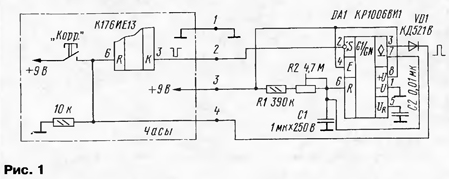
The compensator (Fig. 1) is designed to work in hours performed on chips series C [1].

Every day at 00 hours 00 minutes at pin 3 of chip KIA there is a short low level pulse with a duration of 250 MS. It is used for recalculate the days of the week in the clock and calendar. This signal is fed to the input of single-shot, performed on the timer DA1. A single-shot is triggered and generates the output (pin 3) high level pulse. Its duration is determined timing chain R1R2C1. Using the C1 capacitor with small leakage current, on chip CREW is possible to obtain the pulse duration with high accuracy. In the proposed device the error is not more than 0.3% across the range the duration of generated pulses from 0.45 to 5.6 with S.
The output signal of the single vibrator is input to the correction circuits CIE (pin 6) and produces zero minutes and seconds. This signal resets and counter KIE (on the diagram this connection is not shown) that adjusts with it the accuracy of the phase of the second impulses. Depending on the pulse duration, which is determined by the position of the engine tuning resistor R2, will be to change and RTC correction.
Diode VD1 is used for decoupling. The capacitor C2 allows to avoid the influence of external noise and ripple of the supply voltage, precision timer [2]. Device consumes less than 4 mA at a voltage of 9 V. the Voltage may be in the range of from 5 to 16.5 In [2].
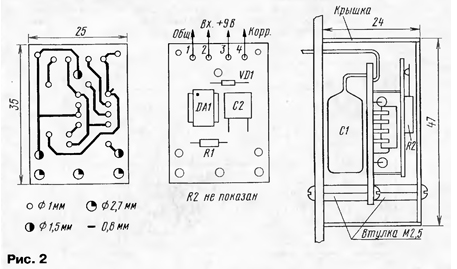
The compensator is assembled on a single-sided PCB of foil fiberglass (Fig. 2).

Fixed resistors R1 - MLT, trimmer resistor R2 - SDR-VM. Capacitor C1 - K73-17, C2 - K10-7 or KM. VD1 - any low-power diode. Length the connecting wires should not exceed 10...15 cm.
The circuit Board is attached to the clock by means of two threaded bushings screws M2,5. Cover of one-sided soldered foil Micarta thickness of 1 mm. It is mounted to the Board with screws through the threaded bushing.
In order accuracy can be adjusted both in plus and in minus, a crystal oscillator configured using the frequency counter the frequency 32768 Hz, as usual, and the frequency 32769 Hz to clock obviously in a hurry 2...3 in day. If the clock is fast, especially to increase the frequency of the generator is not need. Tuning is better done by measuring the period of the second pulses increments of 1 µs. The period value must be 999970 ±5 μs. It's enough coarse adjustment - it does not require long warm-up frequency and hours therefore does not take much time.
With the average position of the slider of the resistor R2, the specified frequency of the quartz generator corresponds to the minimum error at the time of setup. In extreme the provisions of the engine hours are adjusted to +2.5 with or at -2.5 with a day.
Using the frequency measurement mode pulse width all the way around resistor R2 should be divided into the division with step of 0.5 s per day. Thus, for example, if a 10-day clock was behind by 5 with, for their correction need rotate the engine in the direction of plus (to the left in the diagram) by one unit.
The process of adjustment of the clock is as follows. Install the engine in R2 the middle position. At certain times, for example, at 18 h 00 min click correction clock according to the time signal. After 10 days at 18 h 00 min record how many seconds did it for hours. Divide this value by 5, and you get the number of degrees by which to rotate the engine resistor R2.
With a little refinement of the proposed electronic unit can be used in all hours where there is an alarm clock and a reset button seconds. In this case, the start the single vibrator will occur on the alarm.
Literature
Author: D. Kashira, Kirov


