Often the radio there is a need and an electronic timer device that enables or disables external load and a given point time. Schemes such devices have repeatedly been published in Amateur radio publications. They differ from each other in complexity, functional the possibilities of design implementation. In the published article, the author offers another, very simple construction, not made cheap electronic database hours in China.
The most famous of timers is made in the form of attachment to the serial electronic clock, or already have a digital watch (for example, on the basis BIS CIC). A common drawback of most known devices is the relatively large number of elements, having a separate power source, and often also an additional building, often quite large. All this complicates the task of making timer.
The feature of the proposed design is that all parts of the timer are placed in the housing base electronic hours and required improvements design hours minimum. In addition, the timer contains a small number of elements and consumes low current that is allowed to avoid an additional source power (use battery hours).
The timer performs the function of the circuit of the external circuit at predetermined times. The reset is manual. To change settings the device can also obtain the function of the disconnection of the external circuit and short-circuit or disconnection of the external circuit (for example, for supplying trigger any automation).
As the base clock can be used any electronic watch with powered by a galvanic cell voltage of 1.5 V, which has the function alarm and electrodynamic audio indicator. In the described design applied digital pocket alarm clock "TRAVEL CLOCK" Hong Kong production.
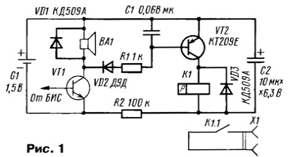
Schematic diagram of the timer shown in Fig. 1.

Added items shown line of increased thickness. The device comprises an input circuit R1C1, amplifier DC on the VT2 transistor and the output key made on relay K1. The timer provides a closure (or opening) of the external circuit when triggered clock / alarm clock. Galvanic isolation of the output circuit connected to the connector X1 provides high noise immunity of the device.
The timer feature in that it employs a special relay called relay with magnetic fixing. It differs from the conventional in that the anchor is able to remain in released and pulled even in the absence of the current in the coil. Therefore, the energy of the power source is consumed only when status relay, which greatly improves the efficiency of the device.
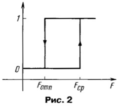
The principle of operation of this relay is as follows. Feature of any relay has a pronounced hysteresis. This means that to switch the relay requires a large magnetodiode force (MMF), than that which is sufficient to his retention of the armature in the energized condition. Schematically, such a characteristic depicted in Fig. 2.

Here x-axis is the value of MDS winding F, and the vertical axis is conventionally depicted points corresponding to the pulled (1) and inactive (0) state of the relay armature. In conventional relay MDS trigger Favg and MDS release Fотп greater than zero and, therefore, when the power of the coil it can only be in the released condition.
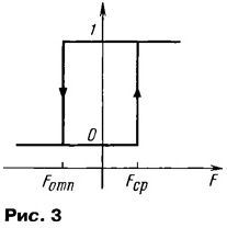
In relay with magnetic latching, except MDS winding, there is another extension MDS created by a permanent magnet, and its value more MDS release, but less MDS activation. Therefore, if the relay coil can to be in the released condition of the armature, as MDS magnet insufficient to trigger and pulled, since the MMF of the magnet is sufficient to hold the armature in the energized condition.
To transfer the relay from one state to another must pass through it winding short current pulse of a mark. With MDS or winding stacks with MDS magnet and the resulting MDS becomes sufficient to the relay or subtracted - in this case, the resulting MDS becomes less MDS release. Feature relay with magnetic latching shown in Fig. 3.

The timer works well. When the signal from the base clock is not supplied, the transistor VT2 is closed, the current through the relay coil does not leak and it is located in one of stable States (e.g., open, for further clarity will be be seen case when the timer runs on start-up). The Capacitor C2 is charged via the resistor R2 to the supply voltage.
When your alarm goes off base hours on their audio indicator BA1 begin be filed a series of rectangular pulses with a frequency of about 1 kHz. These impulses pass through the chain VD2R1C1 open transistor VT2-as a result, the capacitor C2 is discharged to the coil of relay K1, forming a current pulse. Then the relay is actuated, its contacts K1.1 are closed and remain closed, since the armature is attracted by the magnetic flux of the permanent magnet. After discharge capacitor the current through the coil drops to the value limited great the resistance of the resistor R2, and this is achieved by the high efficiency of the whole device.
For opening contacts of the relay (reset state) is used additional external permanent magnet which is moved to relay outside the watch case so that his MDS is subtracted from the total MDS relay, causing it to release.
The VD1 diode prevents over-voltage in the winding of the sound projector BA1. When no diode failures in performance resulting impact on BIS clock pulse overvoltage. A similar function is performed by the diode VD3.
The timer is applied to the following parts: resistors ULM, capacitors KM (C1), K53-14 (S2). They can be replaced by other compact with suitable parameters. Capacitor C2 should have minimal leakage. Diode VD2 needs to be germanium, silicon diode may not open at low amplitude signal (for example, when a partially discharged cell), the remaining diodes - any small-sized, for example, series CD, CD, KD521, KD522, D. Transistor VT2, in addition to small size, should have a small reverse current collector and, preferably, the low saturation voltage. Suitable, for example, transistors series CT, CT. These requirements are determined by the minimization of current consumption.
Relay self-made, based on reed switch CAM-2A. The relay coil is wound on a frame made heavy paper and contains 1500 turns of wire sew with a diameter of 0.1 mm. Length winding (the distance between the sidepieces of the frame) - 17 mm, inner diameter of the frame - 3 mm. the Armature winding is put on the middle of the bulb of the reed switch. Resistance winding got about 70 Ohms. To create a DC bias is used small permanent magnet.
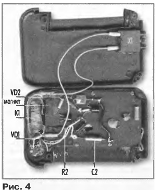
Installation of the timer shown in the photograph (Fig. 4).

The relay is placed in a free the space around the sound emitter and is secured with a compound (for example, paraffin). The remaining elements of the device are placed on top of card hours. Installation hinged, through the use of connecting wires. The fastening elements to the Board and simultaneously electrical connection with the base clock is done using the findings of the elements of C2, R2 and VD2. Conclusions passed through the bore in Board holes from the back side soldered to the corresponding printed paths. If the installation will be stiff enough, items can be additionally fixed by means of the compound. The arrangement of the elements and holes in the circuit Board need to be clarified in relation to the PCB tracks on the Board a particular instance hours.
To connect the external circuit in the case of the watch is set small socket, for example, block MGK-1. Its body is carefully ground off to a thickness of 5 mm and glued in the lid hours, pre-cut in it excavation for sockets. Connection with the findings of the reed switch are a pair of flexible wires. It is also possible and sealed connection with the external circuit, without the use of the connector.
An external permanent magnet is used to return the relay to its original state, it is desirable to perform, for example, in the form of a keychain, designed to be his gift to relay the same pole. The design of the keychain is not included, as it depends on the size and shape of the applied magnet.
Timer setting is to set the position of the permanent magnet. For this to the contacts of the reed switch connect an ohmmeter-tester and slowly bring the magnet to the reed switch. At the moment of contact closure note the position of the magnet and slowly move the magnet away from the reed switch. Note the position of the magnet at the time of disconnection contacts and then fix the magnet on the Board between the two marks.
Then check the relay operation is as follows. When you installed the battery briefly short the findings of the emitter and collector of the transistor VT2, the relay should work and stay in the pulled condition. If not triggering occurs, it is necessary to swap the terminals of the winding. Final check the timer is carried out by a signal of the basic clock. Some types hours has forced signal, e.g., clock, TRAVEL CLOCK" he called while pressing the left, middle button, when this all segments are lit indicator and the beep sounds.
In order for the timer worked on the opening, you need to swap the conclusions relay coil. Then when the timer will be opening reed relay, previously closed by an external magnet.
To obtain the function short-circuit the magnet is mounted so that MDS was not sufficient to hold the contacts closed (for second mark). In this case, the relay K1 operates as a conventional polarized relay. Function briey interrupting the gain by setting the magnet before the first label (so that its MDS was sufficient to trigger the reed switch) and changing sometimes the terminals of the winding.
Because in the last two cases, the relay has a higher current response should be to check the reliability of its operation at a lower supply voltage and, in the case need to rewind the coil with a thicker wire (to reduce resistance). If time is of the closed (open) state is not enough, should be applied to the capacitor C2 with a larger capacity.
The required operating time of the timer set in the usual way - by choice the relevant time on the alarm clock. On and off timer carried out by on/off of the alarm on the base hours. Due to the small consumption current timer (in standby mode, it is determined only leakage) of the individual's power is not provided. Need to make sure that the clock was off, all the other functions, making sound the signals (e.g., alarm sounds every hour), otherwise it will happen the false positive. Return relay external magnet should be performed after stopping supplying the clock beep, otherwise immediately after refund will occur re-triggering the timer.
The timer can be used, for example, as an alarm clock (when the volume the original sound of the radiator is not enough), while the relay contacts are included in chain external sound emitter. You can also use two-winding doorbell, then contacts are connected to its secondary (low voltage) coil.
Attention!!! Isolation relays are not designed for the supply of the mains voltage. When you want to control high voltage loads should be used additional switch.
Author: D. Volkov, Shakhty, the Rostov region.


