Following the scribble (scribble a lot, I warn you) the Cat (meow!) will try to clearly explain - how in one night to make a remote control audio - video complex, bude like this you have.
There is such a Corporation called TOSHIBA - heard somewhere, right? But in this Corporation is the separation of semiconductors and the electronic components. And that's it Department and warning in advance released three chip - TC9148P, TC9149P, TC9150P. In fairness I must say that this vanity was quite a long time - years 15 ago, however, mikroshemki was so successful that until now then, the Ura will apply where no hitting.
TC9148P - encoder-transmitter of the CDS.
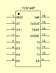
This chip, two transistors and a dozen buttons - all need to build a complete transmitter for sdes. Chip allows you to send 10 different teams with the possibility of extension up to 18 commands. The supply voltage may vary in the range of 2.2 to 5.5 volts. Current consumption in quiescent mode (no button pressed) to 10 µa. Transmission frequency - kg.
Running through the findings:
1 Earth
2.3 Conclusions embedded generator.
4-9 connecting pin for the buttons.
10-12 Conclusions for connection buttons.
13 Assignment of the identification code the transmitter-receiver.
14 is Not used.
15 Output of the transmitter.
When you press the button, the chip generates a corresponding code parcel 12 bits long, built-in generator produces a carrier on a frequency of 38 kHz, and all this mixture is fed to the output.
Next - two chips at once - TC9149P and TC9150P - receivers-decoders SDU.
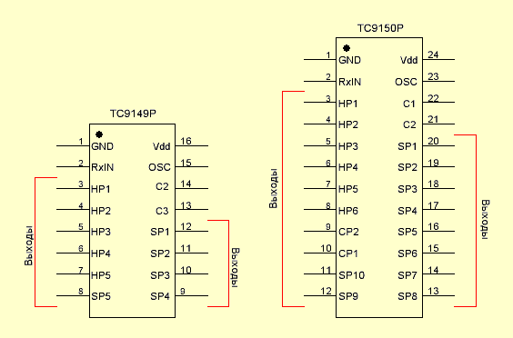
Well it is clear that if there is a transmitter, which is also what it encrypts, then somewhere there must be a receiver, which is something to decipher. These chips are just doing what decode code send the transmitter in accordance with the address switch on/off its outputs. Differ these two, only one the amount of output. I TC9149P their 10 respectively for 10 teams, and TC9150P their 18 - for 18 teams.
Now let us a little bit about the teams themselves.
Figure it is evident that the conclusions that are marked as Outputs, are somehow different marking. And the point here is this. All commands sent by the transmitter divided into three groups: short, long and cyclic. Each group is rigidly attached to the button of the transmitter and the inputs and outputs of the receiver. When you run short commands incorporated the findings of the decoder, labeled as SP (Short Pulse) and they are as follows:
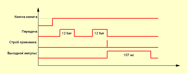
When you press the button of transmitter, formed two same code parcels 12 bits long. The decoder receives these parcels, calculates the checksum and if all is well, issues the gate pulse, on the arrival of which the corresponding output appears logical unit. A high level at the output remains in the approximately 107 msec. then the output is again set in the initial state is a logical zero. Moreover, it is not depends on - released if the button on the transmitter or not. For repeated execution teams need to press the button on the transmitter.
Such teams can be used for example to turn on / off the power of equipment MUTE mode or ST-BY.
When executing a long command outputs are activated decoder, denoted by HP (Hold Pulse) and work as follows:
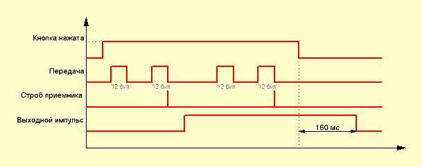
After pressing the button of transmitter, it starts to produce the sequence of paired 12-bit pulses. After treatment the decoder of the first pair and the issuance of the Gating pulse output is translated in the high-level state and this state continues until, while the button is pressed the transmitter. Once the button stops to exert pressure, the high-level state continues to remain at the output of approximately 160 MS, then the output goes to the original the state of the logical zero.
Commands of this type can be used when adjusting the volume, tone or anything else like.
There is a third option - cyclic commands - CP (Cyclic Pulse). They are only available in the case of use as a decoder chip TC9150P. Their essence is that the state of output is inverted each time you press the button of the transmitter. Once clicked - the output is turned on, the second time - off.
Now let's see what the output CODE on chip transmitter and finally move on to the slides. I mean, to specific wiring diagrams. Be patient - missed a bit.
In life be happening, including the fact that you will need two or three transmitter to control two or three devices.
And as such to crank, if the transmitter and receiver are exactly the same? For occasion smart heads of these offices came up with to add to code parcel transmitter identification code to the receiver would be able to understand to handle him came the signal, or well it nafik - the signal came from another transmitter. To do this, the transmitter is provided the output CODE, and in the decoder conclusions C(x).
Let's see how it works. First, let's take a couple TC9148-TC9149.
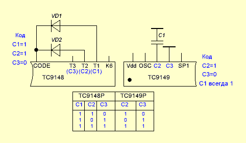
So, in the code transmitter is formed with diodes, connected between the output CODE and the findings of T1-T3. In the decoder similar the code is set by connecting a capacitor between the common wire and conclusions C2 and C3. The table shows the versions of code. It should be noted that in TC9149 code C1 is always 1, and C2 and C3 are set in the aforementioned manner.
Now take a TC9150.
There are quite similar the situation, except that C3 already set and constantly equal to 1, and are C1 and C2.
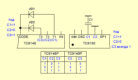
Thus, we can use three transmitter and three receiver in the same room, just upgrading them with different codes identification. Incidentally, it is worth noting that the code 00 is prohibited by the manufacturer and cannot be used.
Fu! Exhaled. A smoke. If you still can't bloody understand - don't worry - now the examples will all become clear (I guess). Let's start with the transmitter.
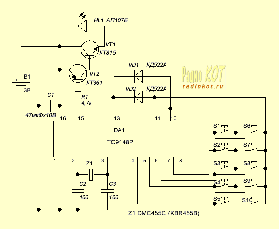
As mentioned above - external components - low. Selected 10 keypad option - to draw less.
Option 10 button, then command - 10 and so our decoder on today TC9149P.
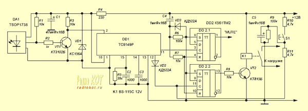
(click to enlarge)
Under this scheme the receiver we perform only two commands - on-off power and switch-MUTE mode on / off. And then another implemented using short commands.
By the way, here's more forgot about the line buttons of the transmitter and receiver outputs. Now fix - looking nameplate:

As you can see, cyclic commands here - to use a different decoder - TC9150P. Well, he can still eight buttons on the transmitter to get hold of. That's just what you this will do - I have no idea.
So share your thoughts on this occasion, and don't forget to ask questions.
Publication: www.radiokot.ru, www.cxem.net


