


")

The scheme timer with separate time setting on and off load. A distinctive feature is the use of the LCD SoG with built-in serial interface (http://www.trt.ru/products/tic/pdf/ML1001.pdf) the type SPI (http://www.trt.ru/products/tic/pdf/segment/TIC8213.PDF) and an independent power supply from a three-volt chem.source (one tablet lithium, a pair of alkaline tablets, etc.). Allowed power from 2.5 to 5 volts. Independent source makes the timer is non-volatile, which means not having to set the time when turning.
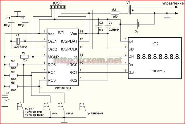
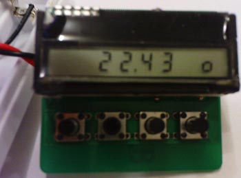
The indicator contains 8 seven-segment ceramist. The current time indication is performed by the Central four digits of the division of minutes and hours for the decimal point. In the right-familiarity shows the current state of the control key by using the subscript zero and one (half height) - zero-off, unit-incl.
The settings are made by four buttons. Hold down the button "setup" for 2…2,5 h leads to a transition into the setup mode. When you enter the mode provides a rst set the current time (hours). When this indication is moved to the leftmost position. Pressing the "min" and "clock" is incremental installation right time. Hold these buttons for more than 2 h leads to the increment of the corresponding value at a frequency of about 2 Hertz. After setting the current time, always recording with a single tap on the button "install". If you want to set the timer on or off, then press on the button "time/on timer/off timer" to select a desired value for the installation. When you switch to the installation of timers display is moved to the extreme right position, and the left subscript zero or one shows a timer at the moment to be installed. How to install timers like time. After setting of EACH TIMER must write the value to memory by pressing "install". In the set mode the timer does not work!
The program is written in ASMe. The source code is available. Controller operation is performed from internal RC oscillator 8 MHz. Clock oscillator 32768 Hz. Most of the time the controller is in the slip. The average consumption of about 5…7 mA. In the set mode the consumption is about 0.7 mA.
As the key used low-threshold MOSFET (IRLML2502, part no bss138 and similar). Button any. Other elements of the SMD. Socket programming with PLS5 order as in PICKit2.
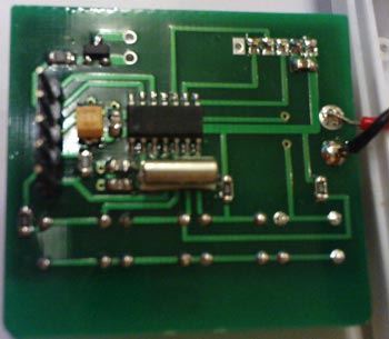
In the attached file you will find a PDF file for Loot (print 1:1, the image is mirrored under the TOP layer).
Reverse side is solid metallization. One jumper. Transitions to the ground soldering through corresponding vias.
Download the ASM source code, firmware HEX and printed circuit boards PDF
Author: mark Yampolsky, M. O., G. Fryazino; Publication: www.cxem.net