


")

Remote control (RC) TV, VCR, satellite receiver, stereo, etc. can be used for on and off lighting and other electrical appliances. For this need to make a special switching device, which is described in the proposed article.
One of the variants of the device designed for remote control applications with using a standard remote control, was described in the article S. Biryukova "the TV remote control manages the chandelier" ("Radio", 1999, № 12). Readers are invited to more simple and versatile variant of such a device that does not require decoding commands the remote control, which can work with any remote, including simple homemade.
For remote control applications used the following algorithm. The remote control serves command (any) and hold the button down for 1 second To short pressing the buttons (for example, when controlling TV) the device does not respond. In order to eliminate the response of the TV trying to operate the device, need to choose an unused button on the remote or use the remote off and the moment of the device. Another option is to use such the remote buttons, clicking on which (in particular) will not result in a change the operation mode. For example, pressing the button to select the channel corresponding to taken at the moment the program will not affect the operation of the TV.
Diagram of the device shown in Fig. 1. Specialized DA1 chip enhances and converts the photodiode signal BL1 into electrical impulses. On the elements DD1.1 and DD1.2 assembled comparator, and on the elements DD1.3, DD1.4 - pulse generator.
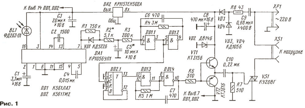
(click to enlarge)
The device status (on or off load) determines the trigger DD2.1. If the direct output of the trigger high level, the generator will work at a frequency of about 1 kHz. The emitters of transistors VT1 and VT2 will arise rectangular pulses, which through the capacitor C10 will be on managing the electrode of the triac VS1. It will open at the beginning of each half cycle the mains voltage.
In the initial state at pin 7 of the chip DA1 logic high is present level, the capacitor C5 is charged through resistors R1, R2 and the input With trigger DD2.1 low level. If the photodiode BL1 received pulses of IR radiation with the RC at pin 7 of the chip DA1 pulses appear and the capacitor C5 will discharge through the diode VD1 and the resistor R2. When the voltage on C5 is reduced to lower threshold comparator output (via 1 or more), the comparator switches and the input trigger DD2.1 will receive a boost. The state of the trigger DD2.1 will change. So way switch the device from one state to another.
Chip DD1 and DD2 can apply a similar series of K, K. VD2 - Zener voltage 8…9 V and a current not less than 35 mA. Diodes VD3 and VD4 - KD102B or similar. Oxide capacitors - K50-35; C2, C4, C6, C7 - K10-17; C9, C10 - K73-16 or K73-17.
Most of the parts of the device are mounted on a circuit Board from unilaterally foil fiberglass, a sketch of which is shown in Fig. 2.
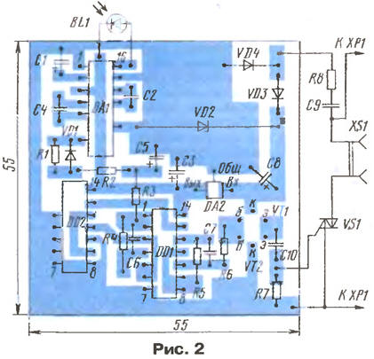
Cost set in a body of insulating material. Resistor R8 and capacitor C9 set method for surface mounting. Triac VS1 with a power and a load more 250 W must be installed on the heat sink.
Establishing device is reduced to the selection of the resistor R2 so that the switch occurred after 1…2 s. If the increase in the resistance of this resistor will cause the capacitor C5 will be discharged to a threshold voltage, it is necessary to use a capacitor C5 capacity, 2…3 times greater, and setup to repeat. The capacitor C6 must be installed in the case the rise time of the pulse coming from the comparator on the trigger is too big and it'll switch unstable.
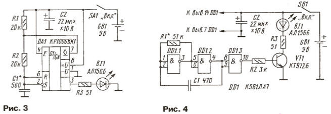
If the console does not allow to control the device without interference to the TV, you can make a homemade remote control, which is a generator rectangular pulses with a frequency of 20 to 40 kHz working for emitting IR diode. Options the remote control on a timer CREW and logic chip shown in Fig. 3 and 4.
Author: I. Nechaev, Kursk